Liquid Gryphon 3
Overview · Ignition · Engine · Feed System · Testing · Reflection
Overview
The Gryphon 3 project set out to achieve the first liquid rocket launch from UK soil. Our goal was to combine the knowledge we had developed from building liquid engines in previous years, and take it a step further to design, and build a full bipropellant rocket. The ultimate goal of LURA's liquid programme is to develop a rocket that can reach the Kármán line — this was just the start.
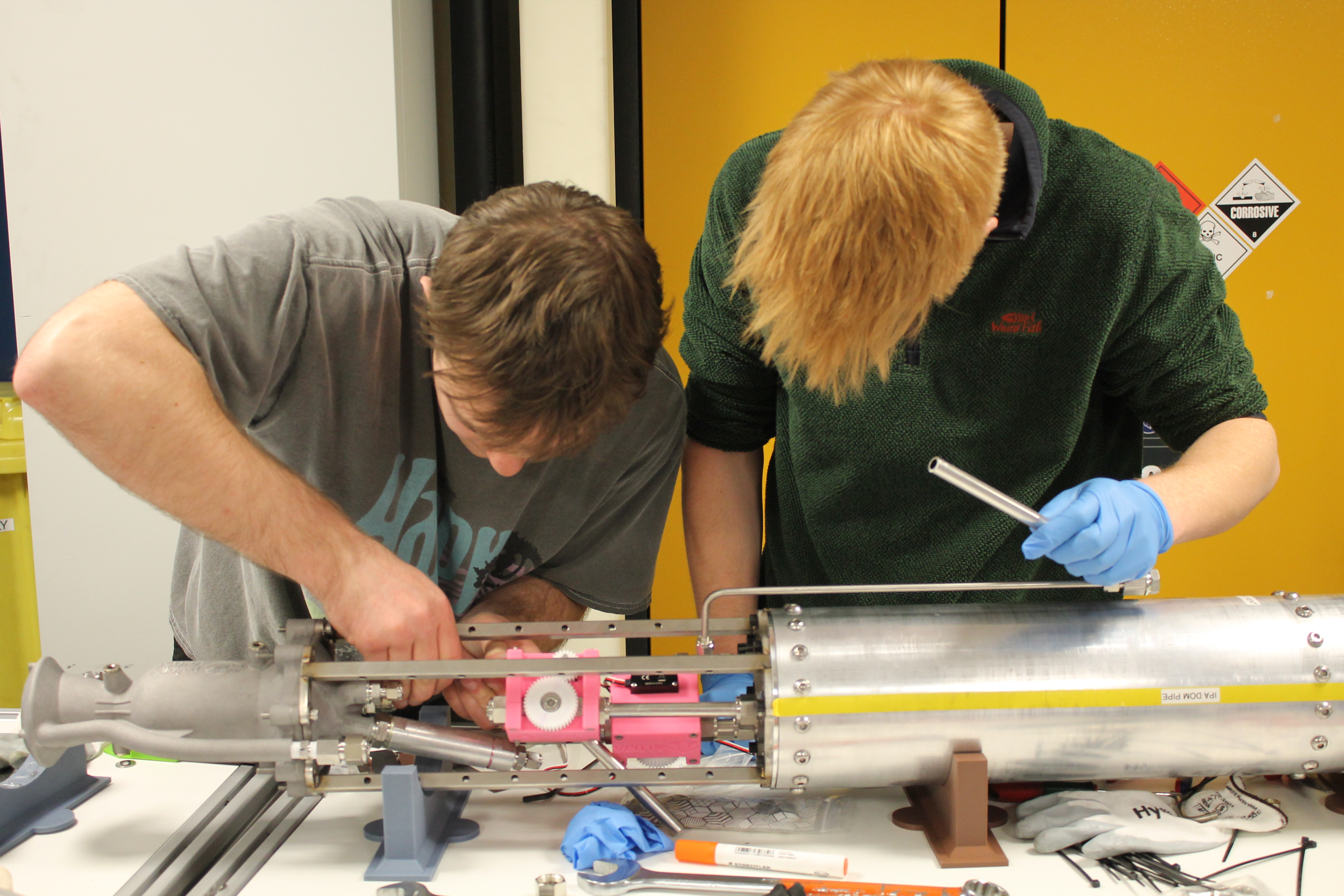
System Overview
- Thrust3kN
- Burn duration3.5s
- Wet mass30kg
- PropellantIsopropyl alcohol/ Nitrous oxide
- Fuel pressurisationRegulated from a nitrogen COPV
- Oxidiser pressurisationSelf-pressurising
- IgnitionSolid rocket cartridge (Estes C6-0)
- Engine3D-printed AlSi10Mg, single pass regenerative cooling
- Injectorox-centred triplet impinging
- Design to fire6 months (with a redesign at 3 months)
Ignition
I started in LURA as a propulsion engineer, responsible for the ignition system. This originally was planned to be a liquid ignitor, developing an in-house test bench alongside it.
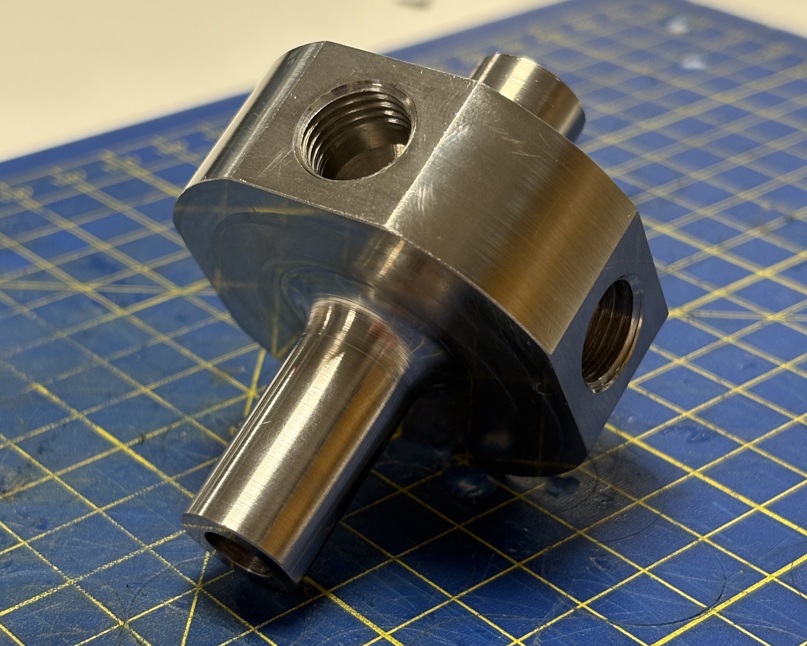
Liquid ignitor V1
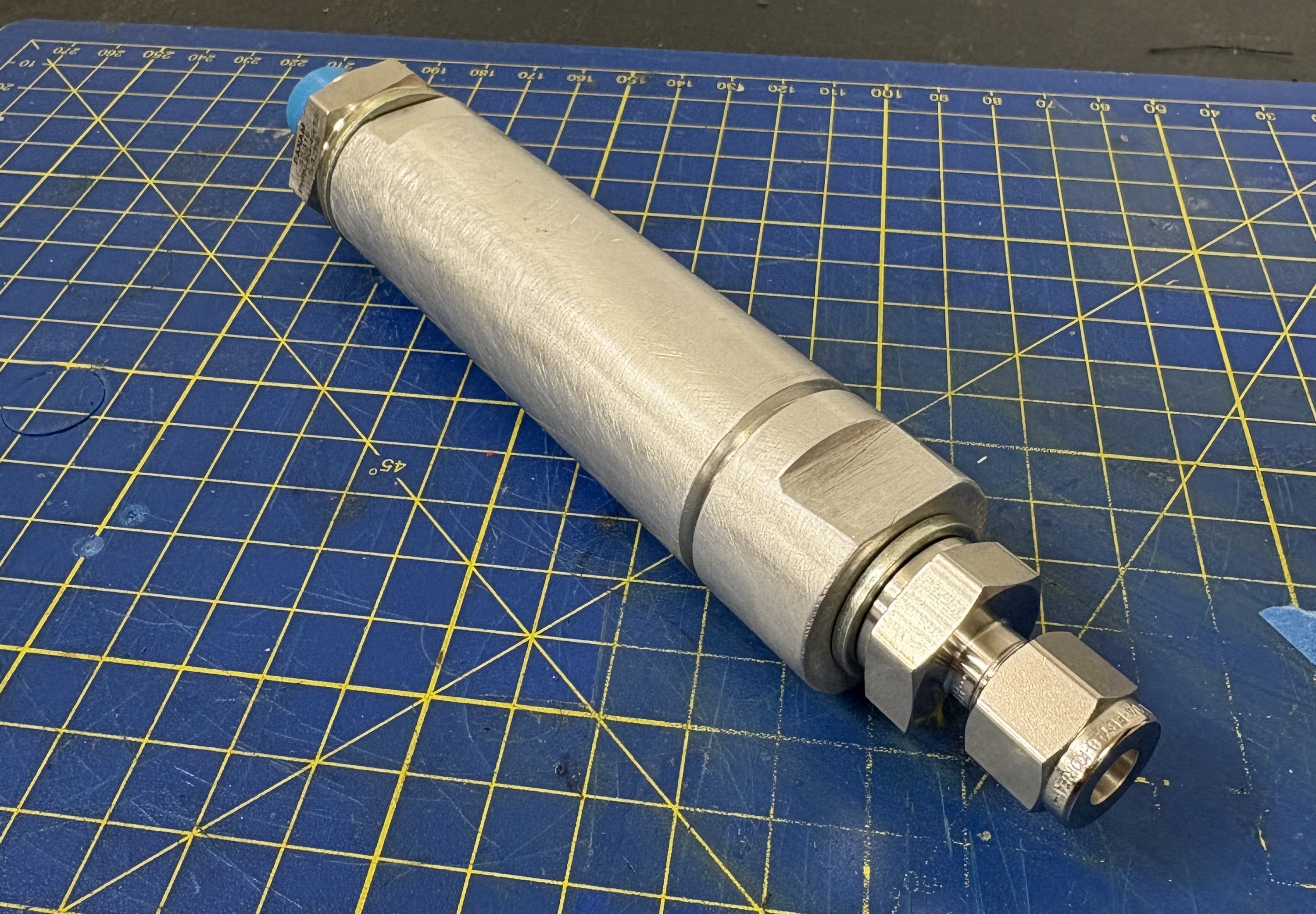
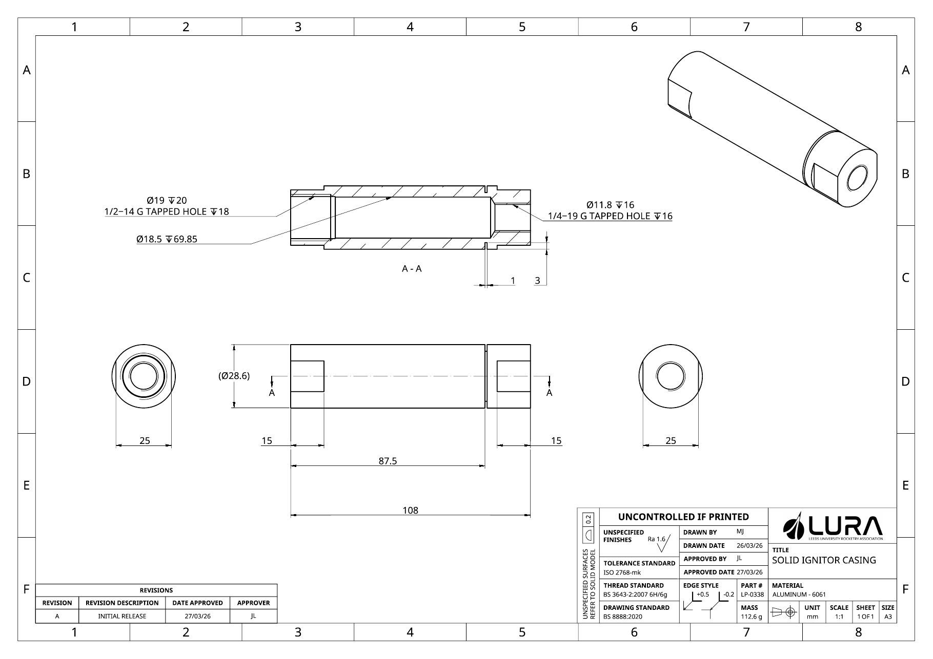
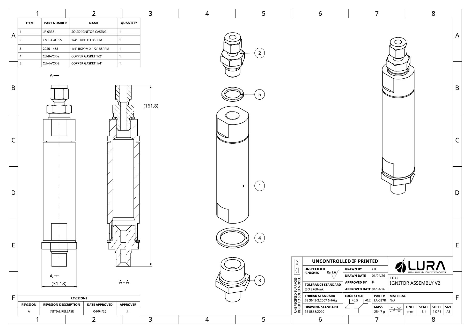
When it became clear that the engine design needed more attention, we pivoted to a simpler solid ignitor. A CATO from a Klima motor inspired a change from stainless steel COTS parts to a custom machined aluminium casing (that we could do ourselves on the lathe) that would fail less energetically, and with a failure point built in so failure would be at a predictable location. A 1/4" BSPP port was machined in the top for a PT to take chamber pressure readings.
Engine
I designed an ox-centred triplet injector for the engine inspired by the requirement for more efficiency than we had seen with our previous years pintle injector. Despite poorer mixing from largely different stream flow rates, the outer fuel orifices would act as a secondary thermal barrier, in addition to our film cooling, to mitigate expected cooling issues.
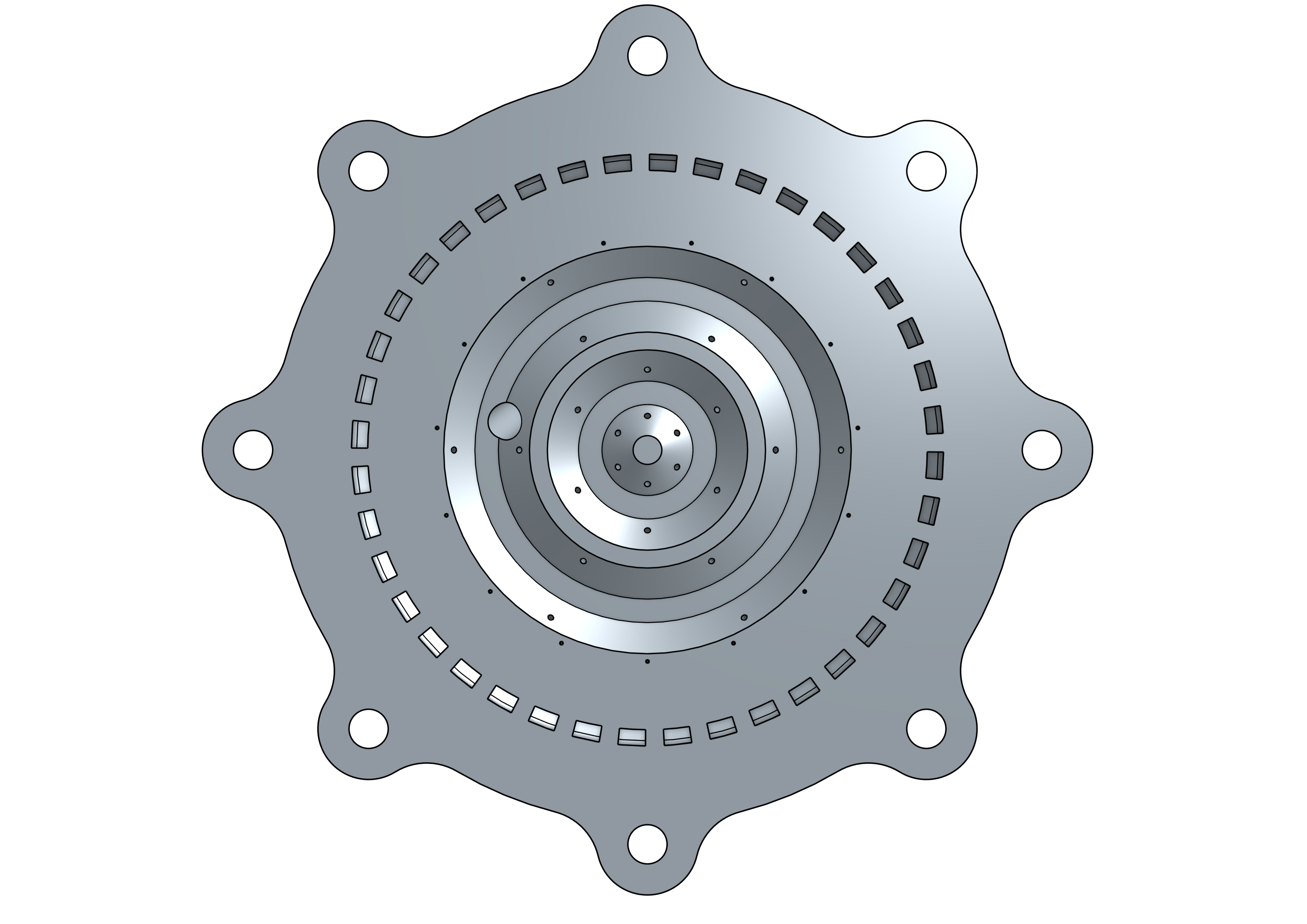
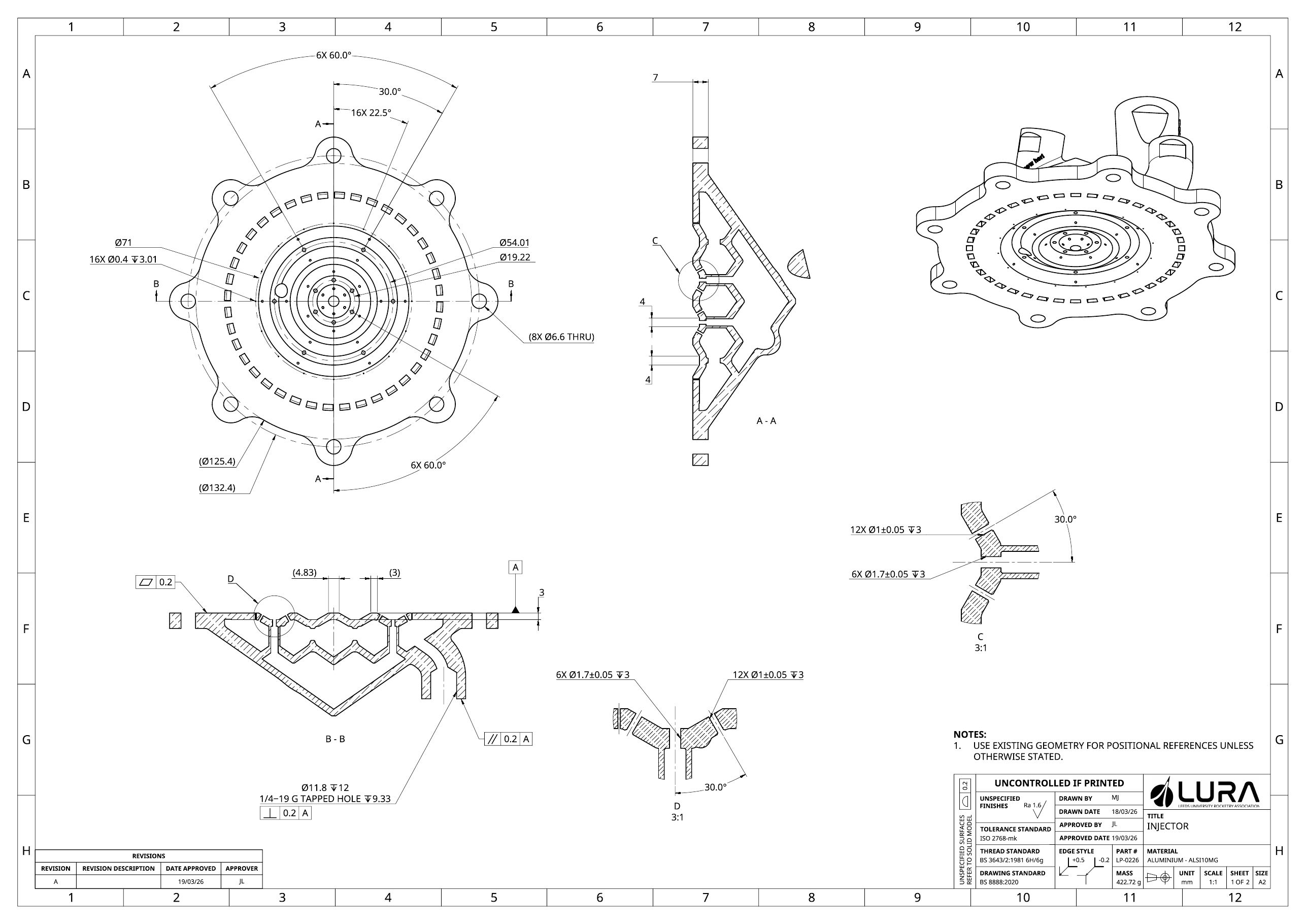
To maximise simplicity of engine integration, the injector was designed as one part. This meant using a complex lattice structure to support the upper (ox) manifold while minimising flow impedance in the lower (fuel) manifold. Channelling oxidiser to the 12 individual injector orifices was achieved using individual downcomers, and the top manifold was fed from an angled inlet that maximised the distributions between elements. Long nights and lots of energy drinks paid off — my CAD skills grew a lot!
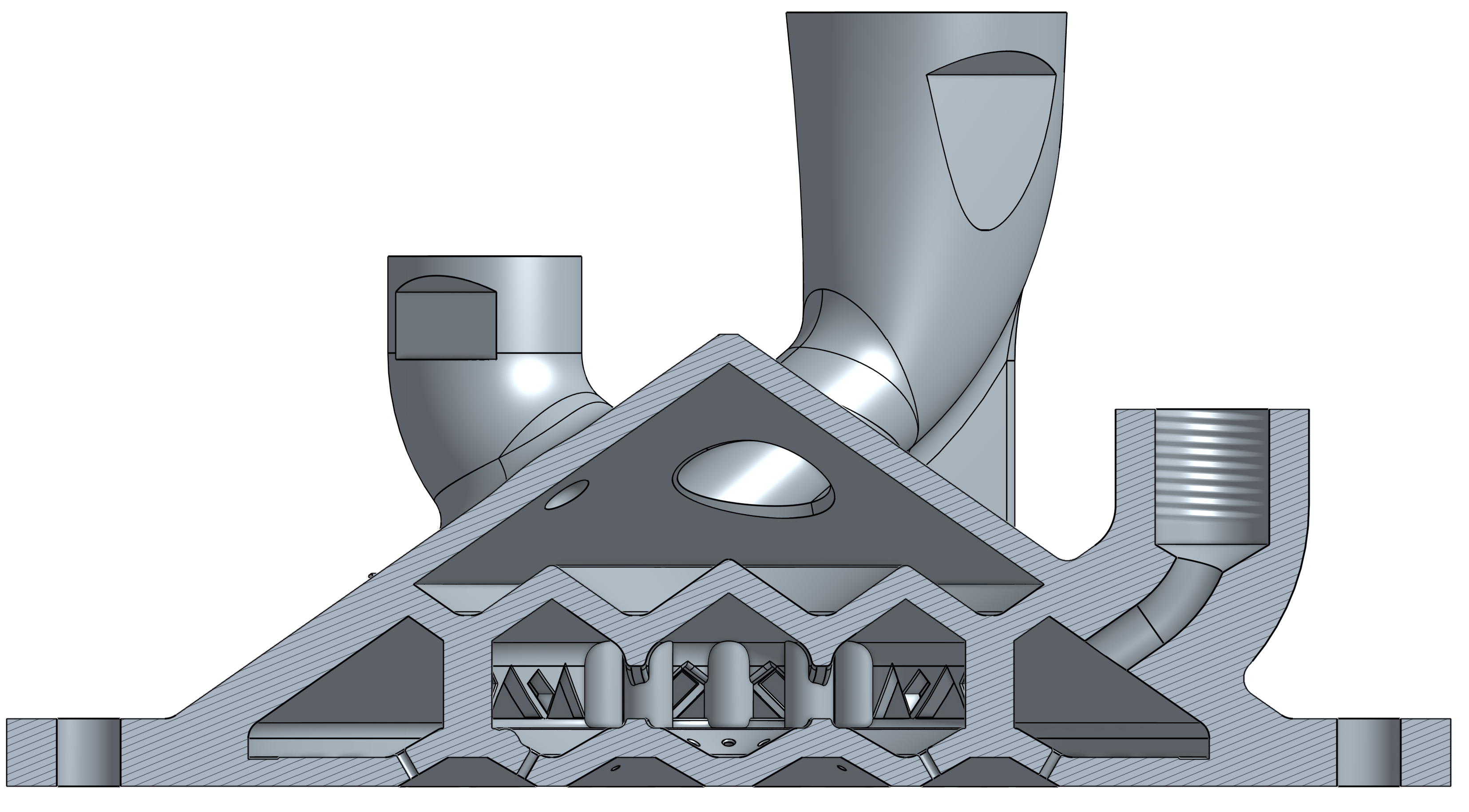
Injector CAD cross-section
The chamber brought interesting problems too. Modelling helical regenerative cooling channels with variable rib thickness was a great challenge where I managed to implement a fairly simple solution with multiple lofts between planes.
Feed System
In February 2026, I became the project Fluid Systems Lead. A team reshuffle allowed us to reflect on our goals for the project — we would need to simplify the design to achieve a summer test/launch. The main changes:
- Engine7kN to 3kN
- Rocket diameter8" to a 6"
Small changes but a big impact. A lot of very valuable learning and planning had been done in the first semester, but now we needed to redesign the entire rocket...
With my teammates helping with simulations, I redesigned the engine CAD in a week, before sending off for print. I wasn't starting from scratch and was able to add in some extra features such as a tapered volute for more even regen flow distribution and ribs for added strength at the throat.
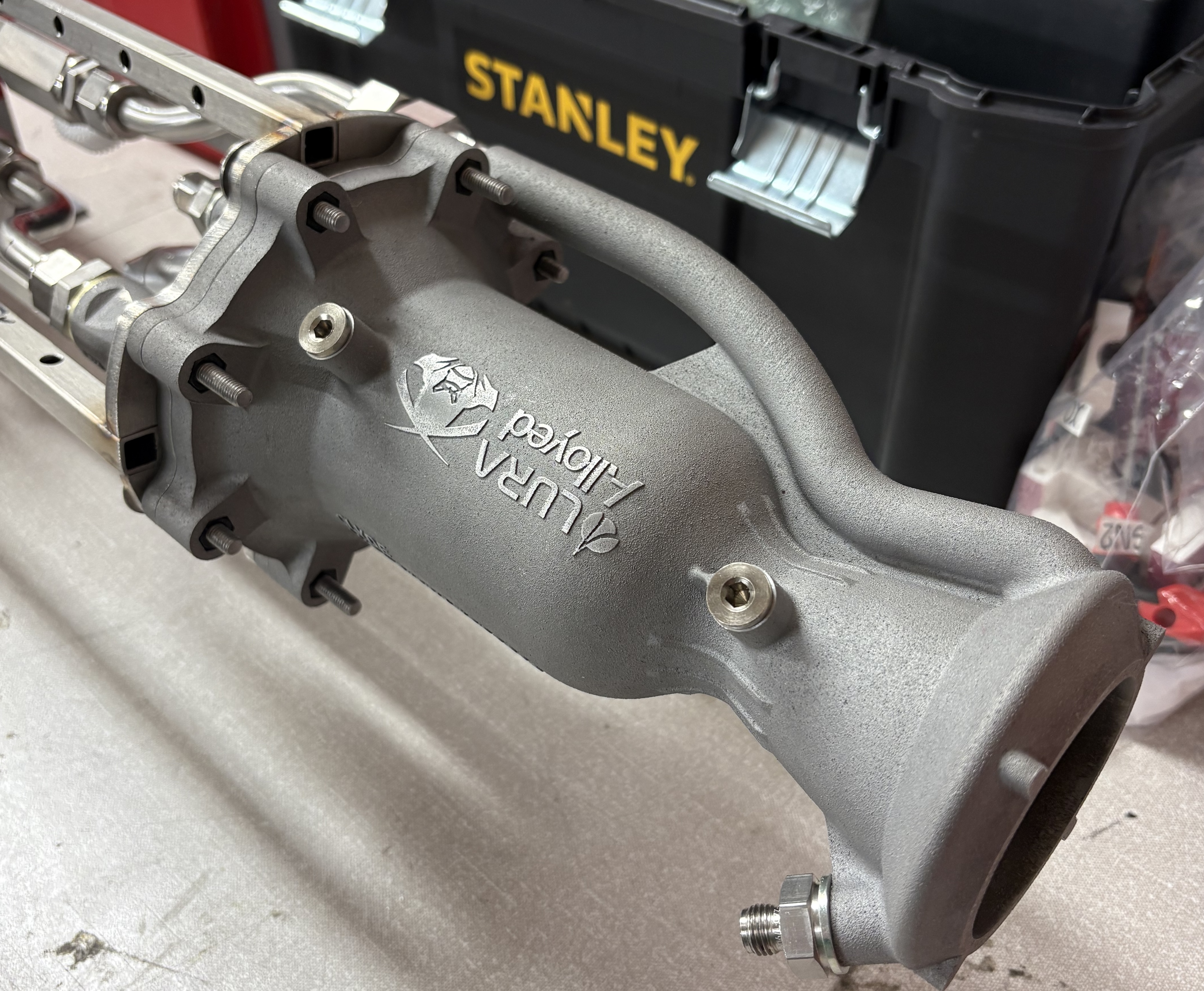
I was then able to fully focus on the development of the rocket's tanks, pressurisation system, plumbing and system integration. The first stage was to work through the full system fluid requirements, building a full Excel sheet to model required volumes, ullages, pressures and flow rates across the vehicle.
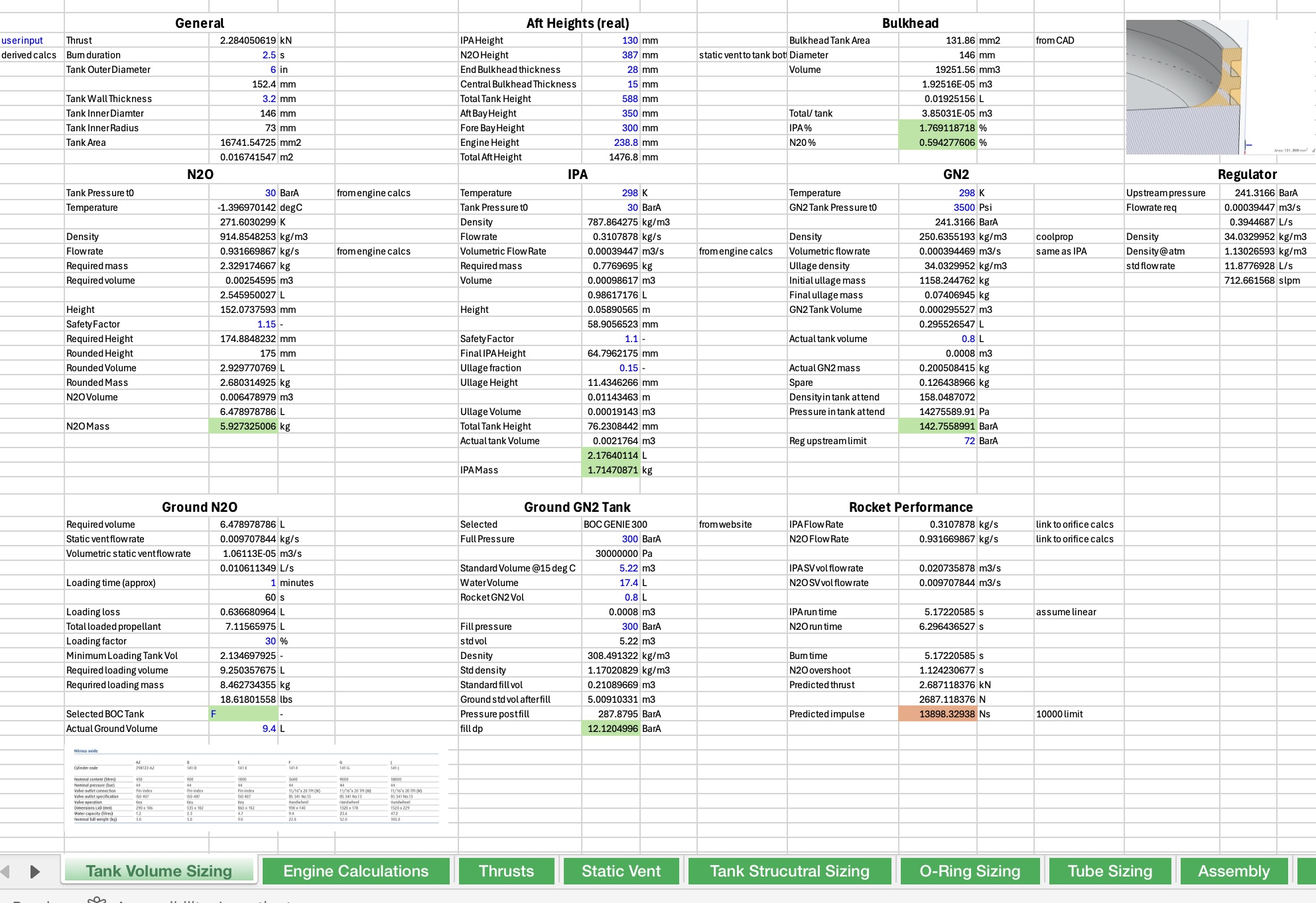
G3 design sheet
For the pressurisation system I sourced a 300Bar paintball tank, and a high flow scuba regulator that were perfect for the application. All fittings except AN fittings on the COPV were Hylok as they are significantly cheaper than standard Swagelok parts and I haven't had any issues with them! The forward bay also included a fill port, and a PRV for the IPA tank to protect from a regulator failure and tank overpressure.
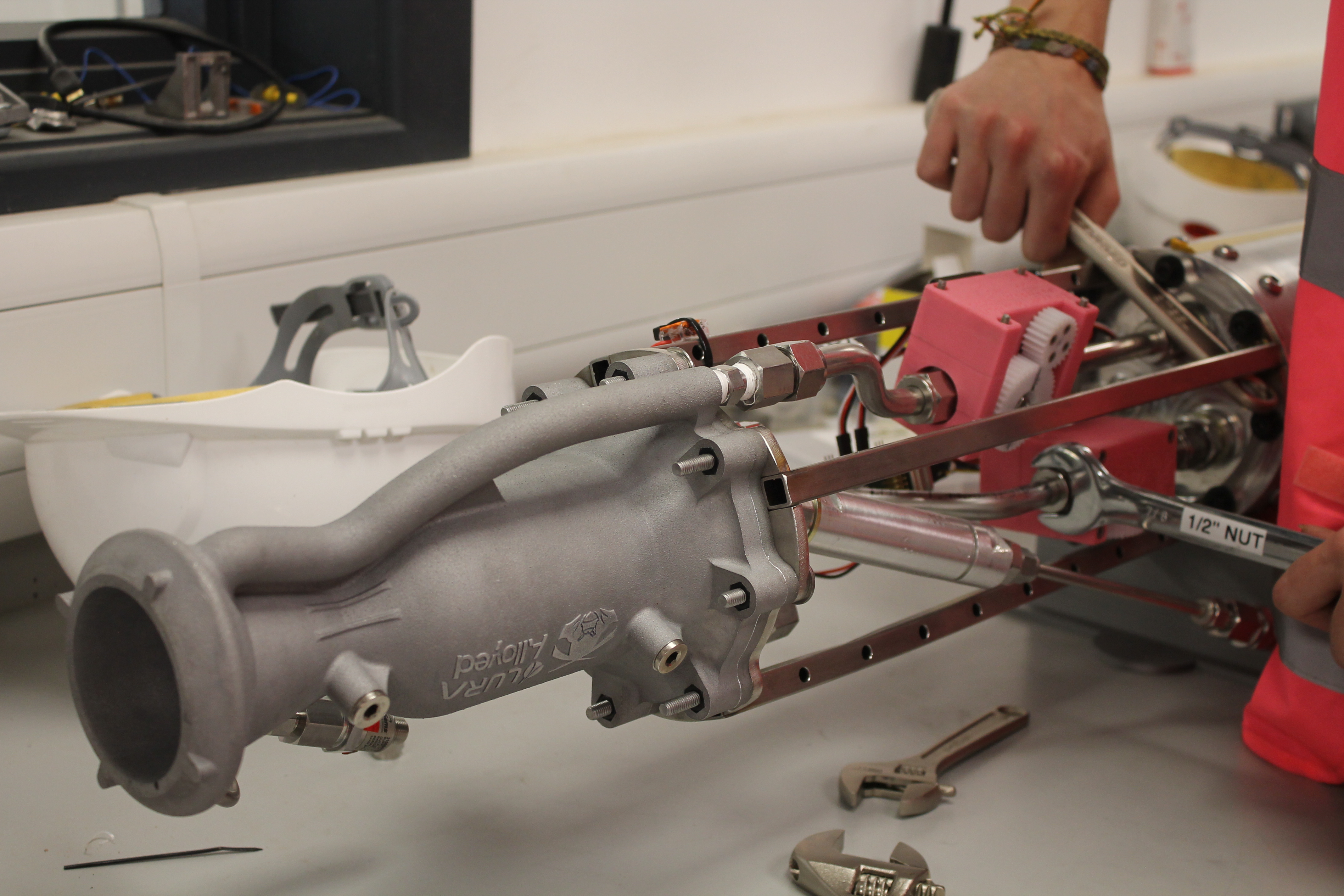
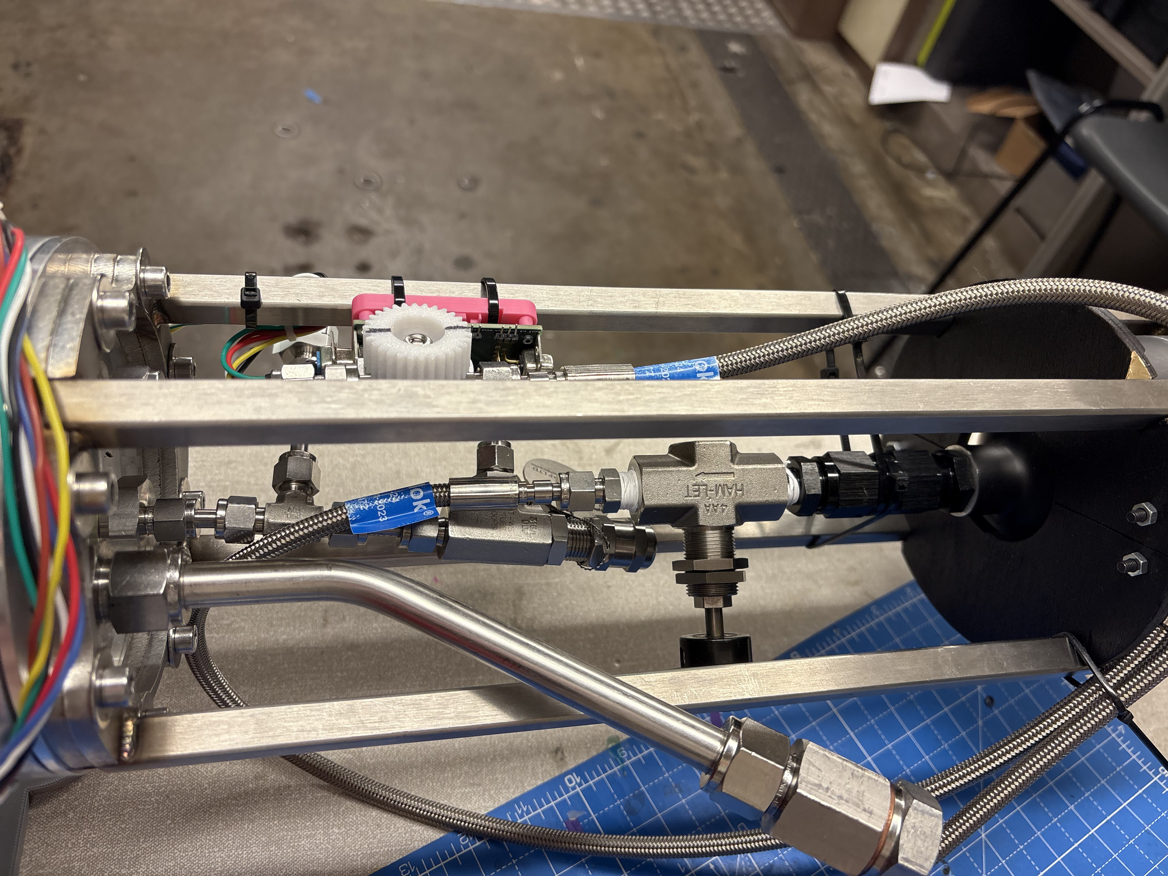
Aft and fore bay plumbing (minus the regulator)
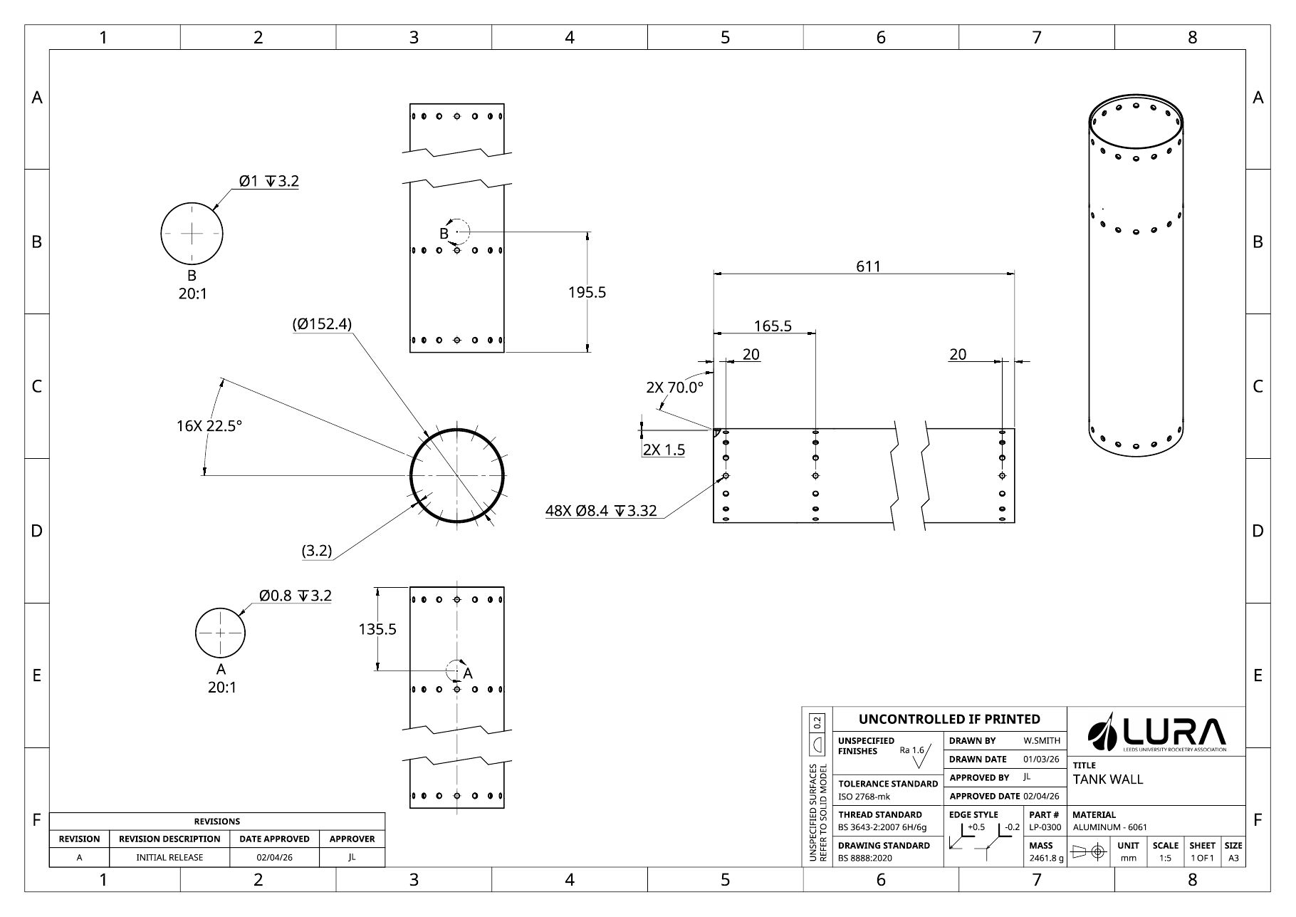
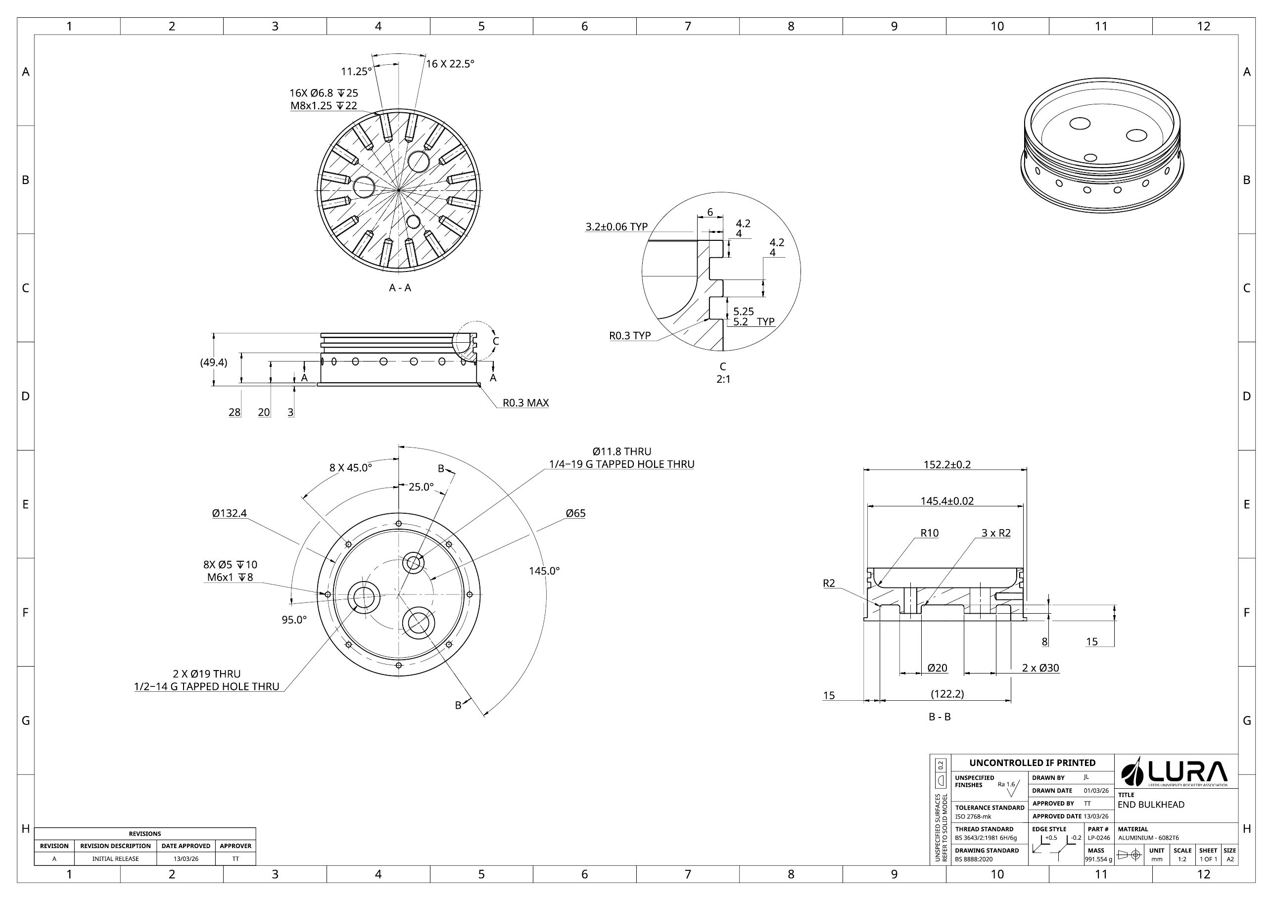
The custom tanks were designed to be stacked on top of one another, with a common outer wall and a common bulkhead separating them. Each tank had a static vent to allow depressurisation if contact was lost with the rocket (in Mojave they just shoot the tank!).
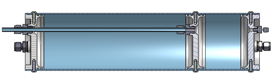
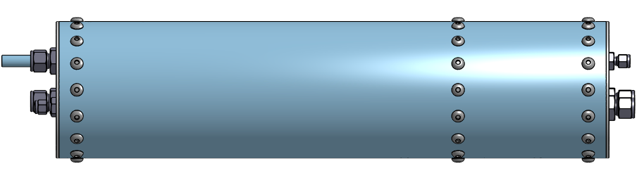
Tank CAD
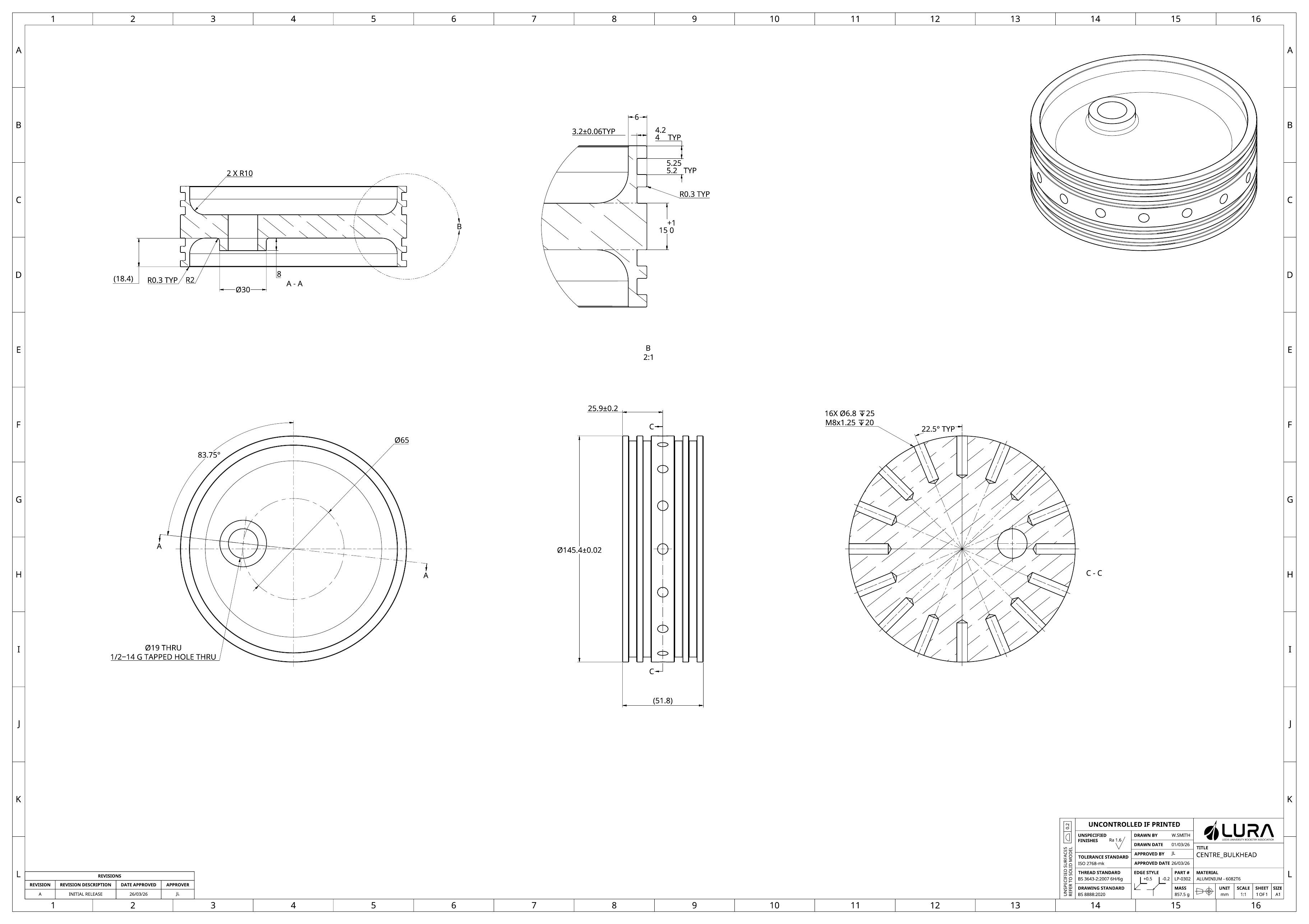
The most unique challenge of the tanks was drilling the 16 radial holes required, as they had to be clocked to the threaded bulkhead holes on the inside. To drill the holes, I 3D-printed a PLA drilling jig with an 8mm drill bushing insert to protect the jig from the cutting edge and increase the lifespan of it — this took a long time to get right, but very satisfying when it worked!
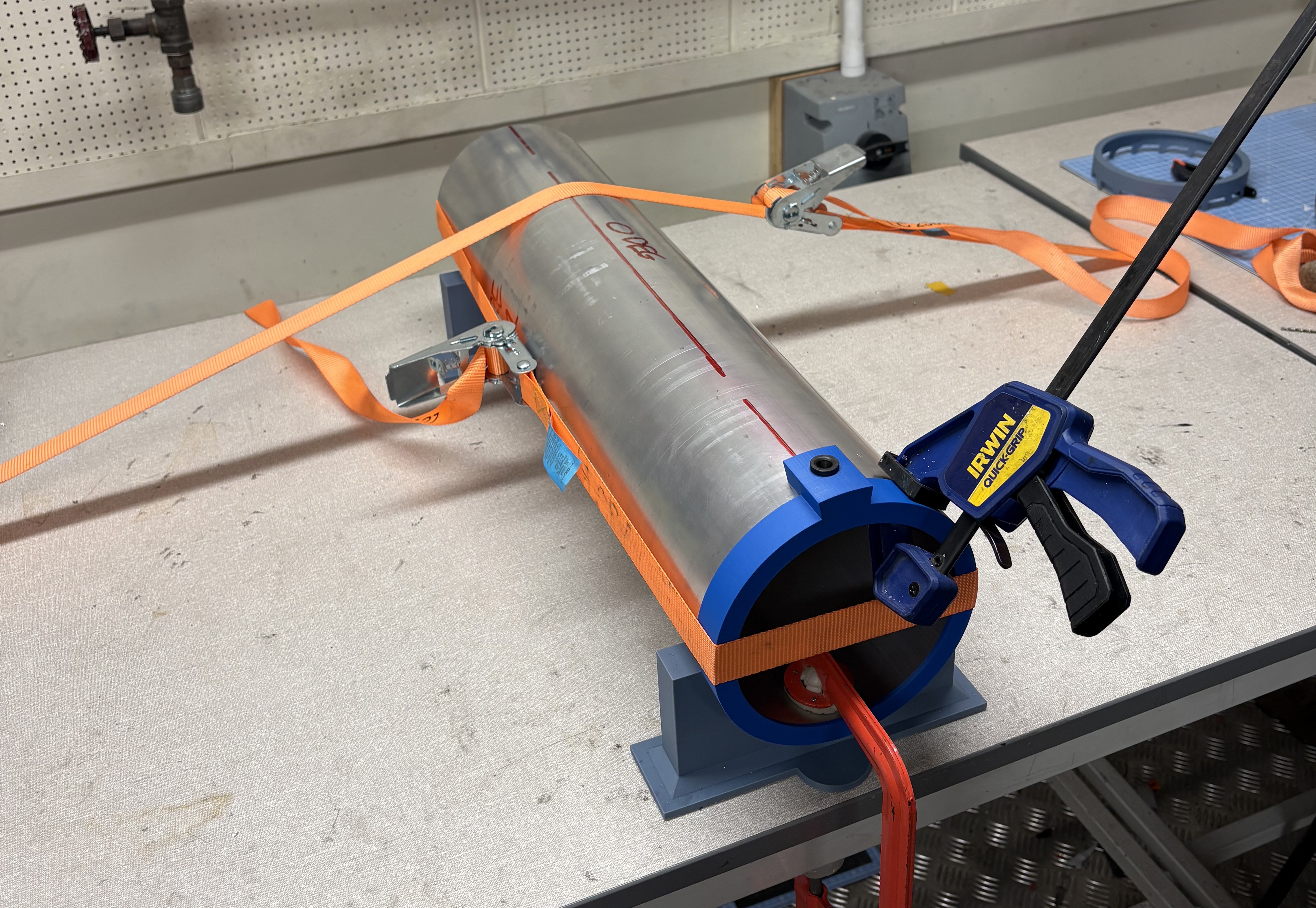
3D-printed drilling jig
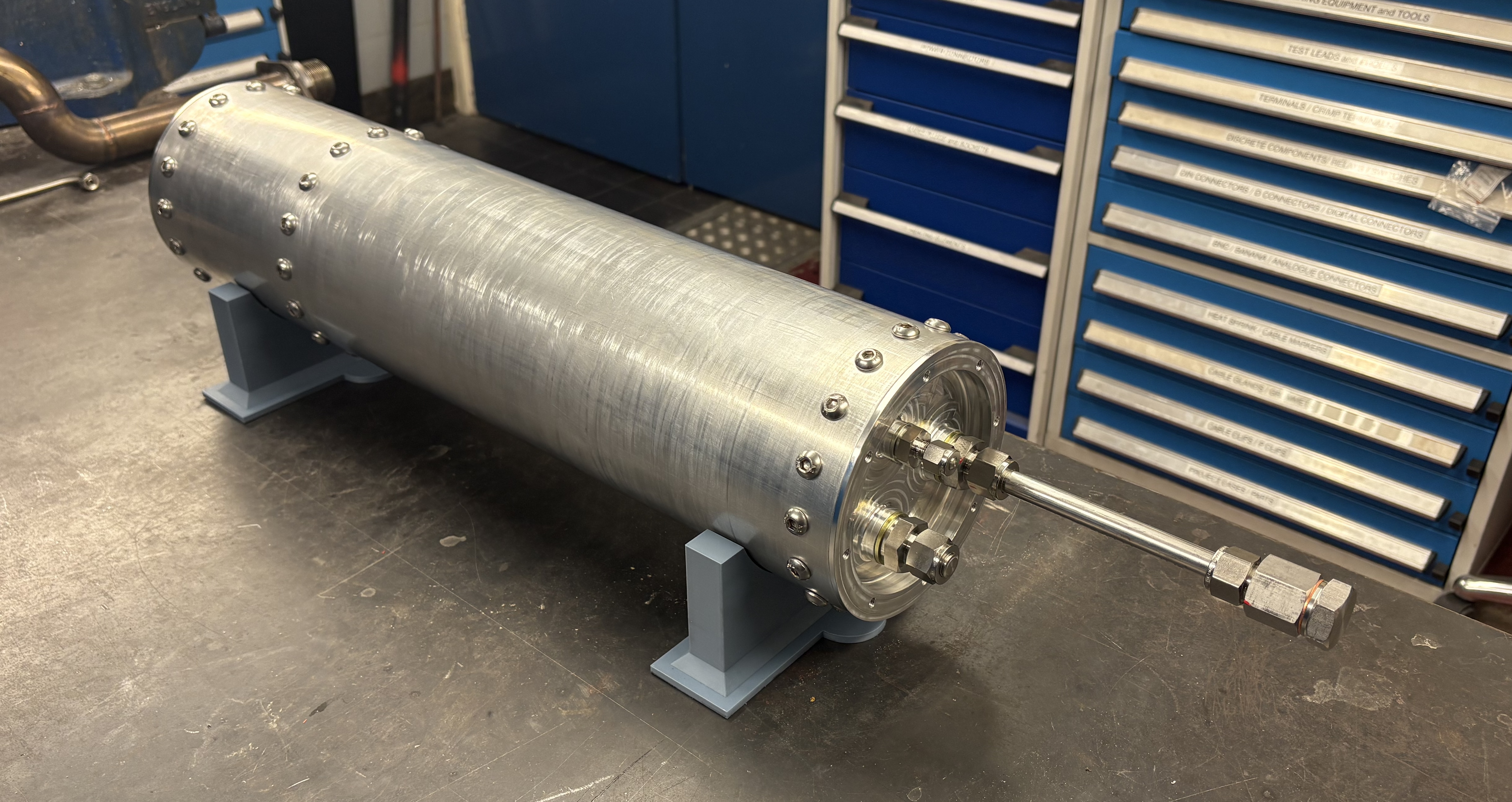
And the final tank was assembled!
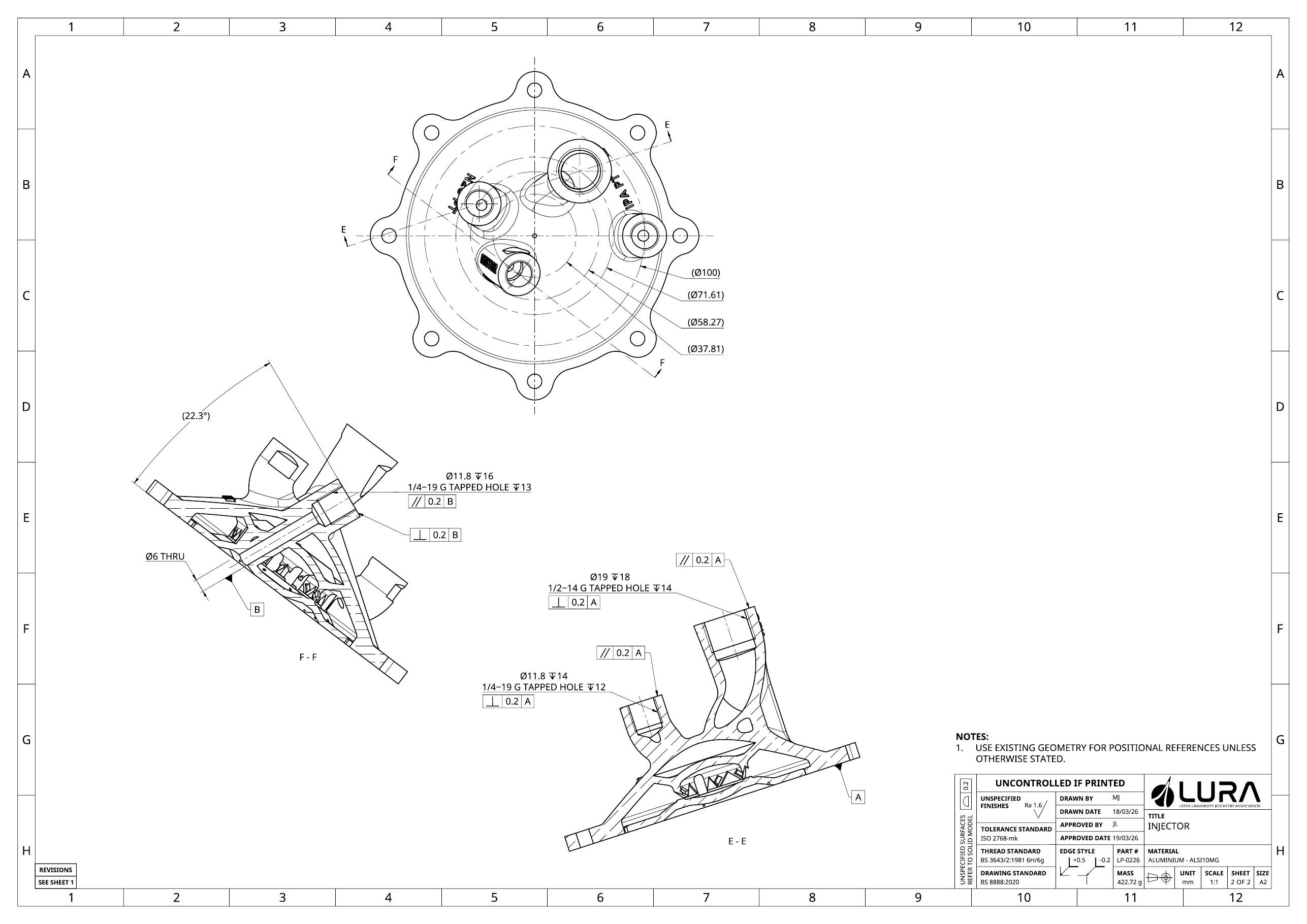
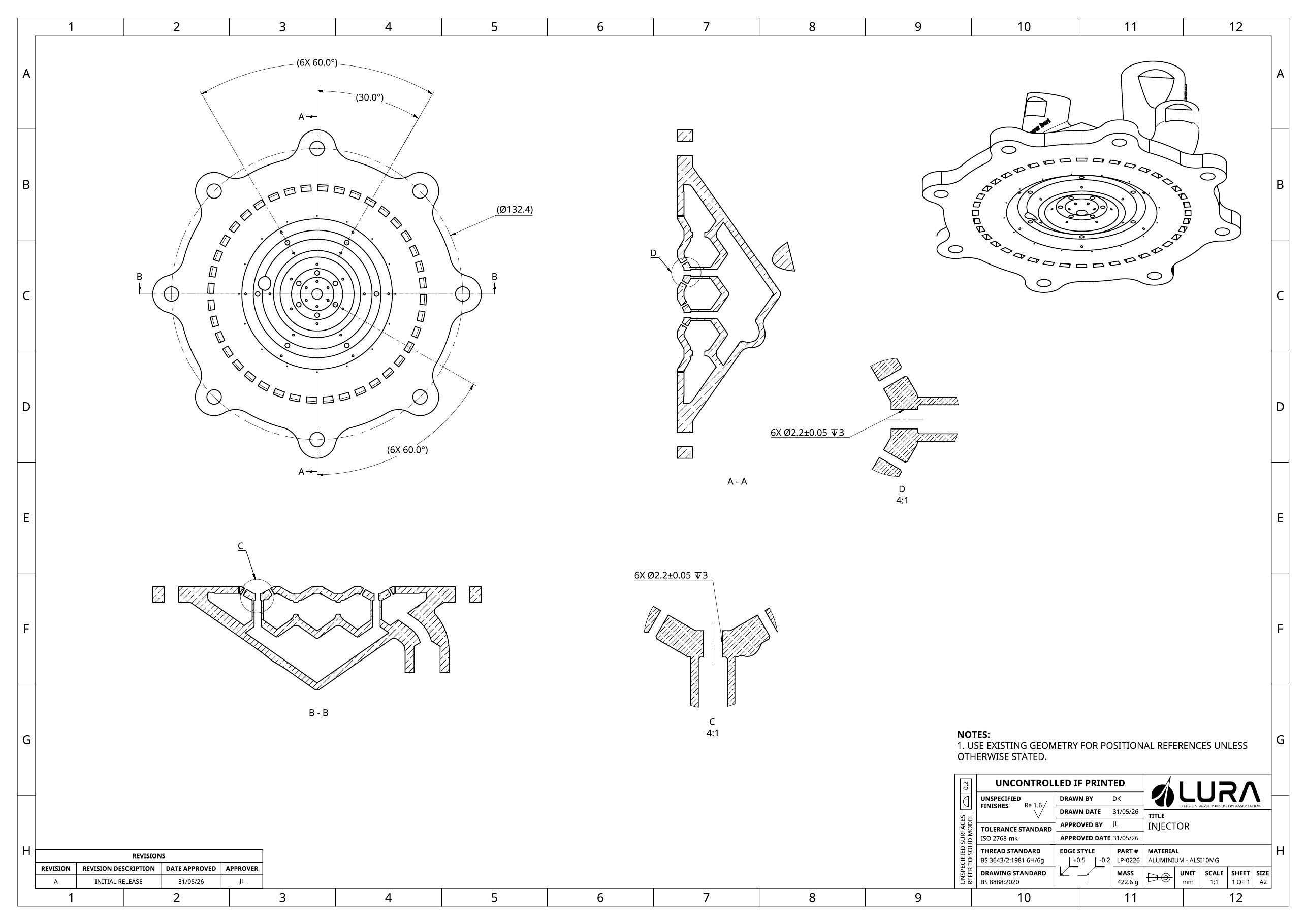
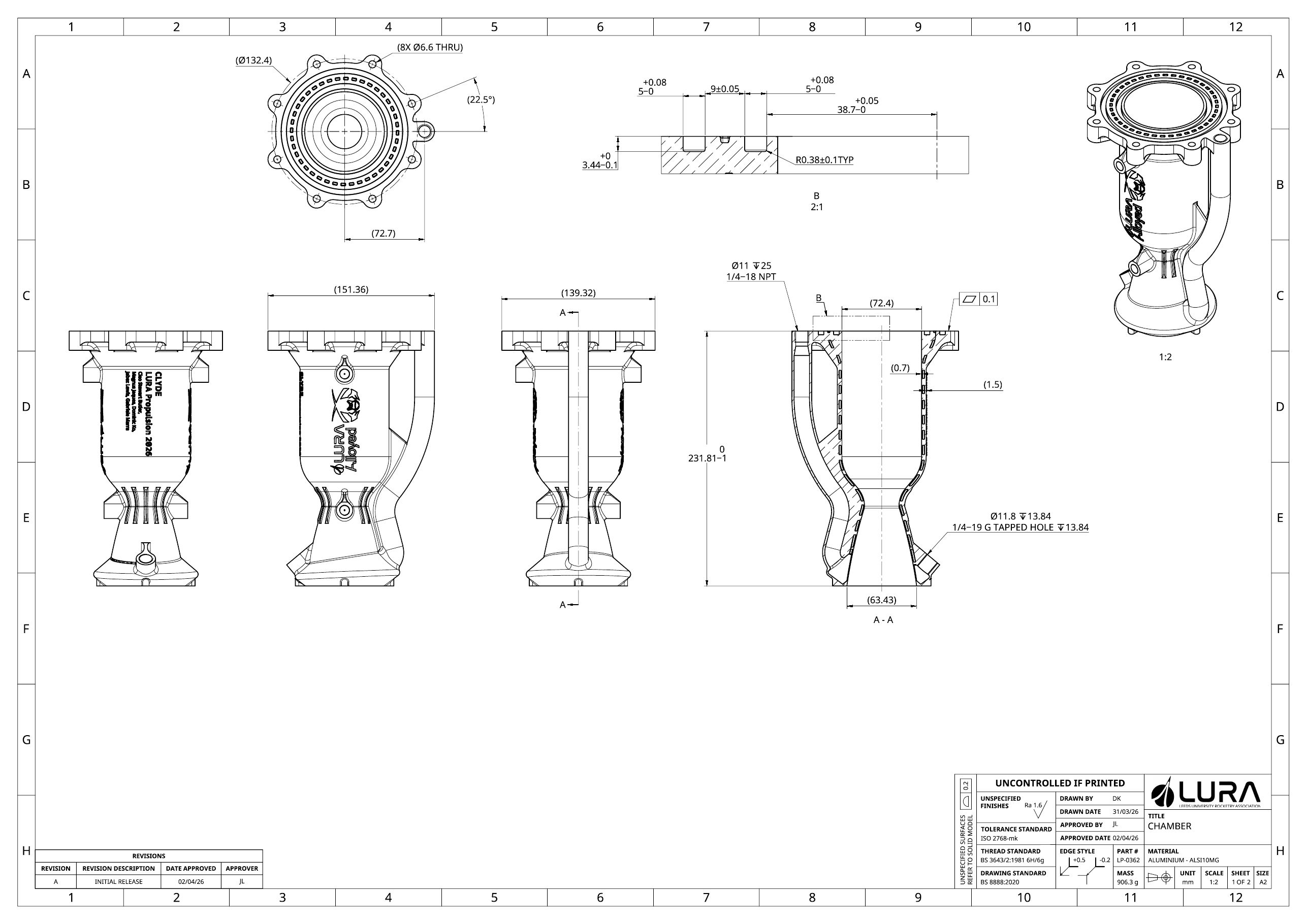
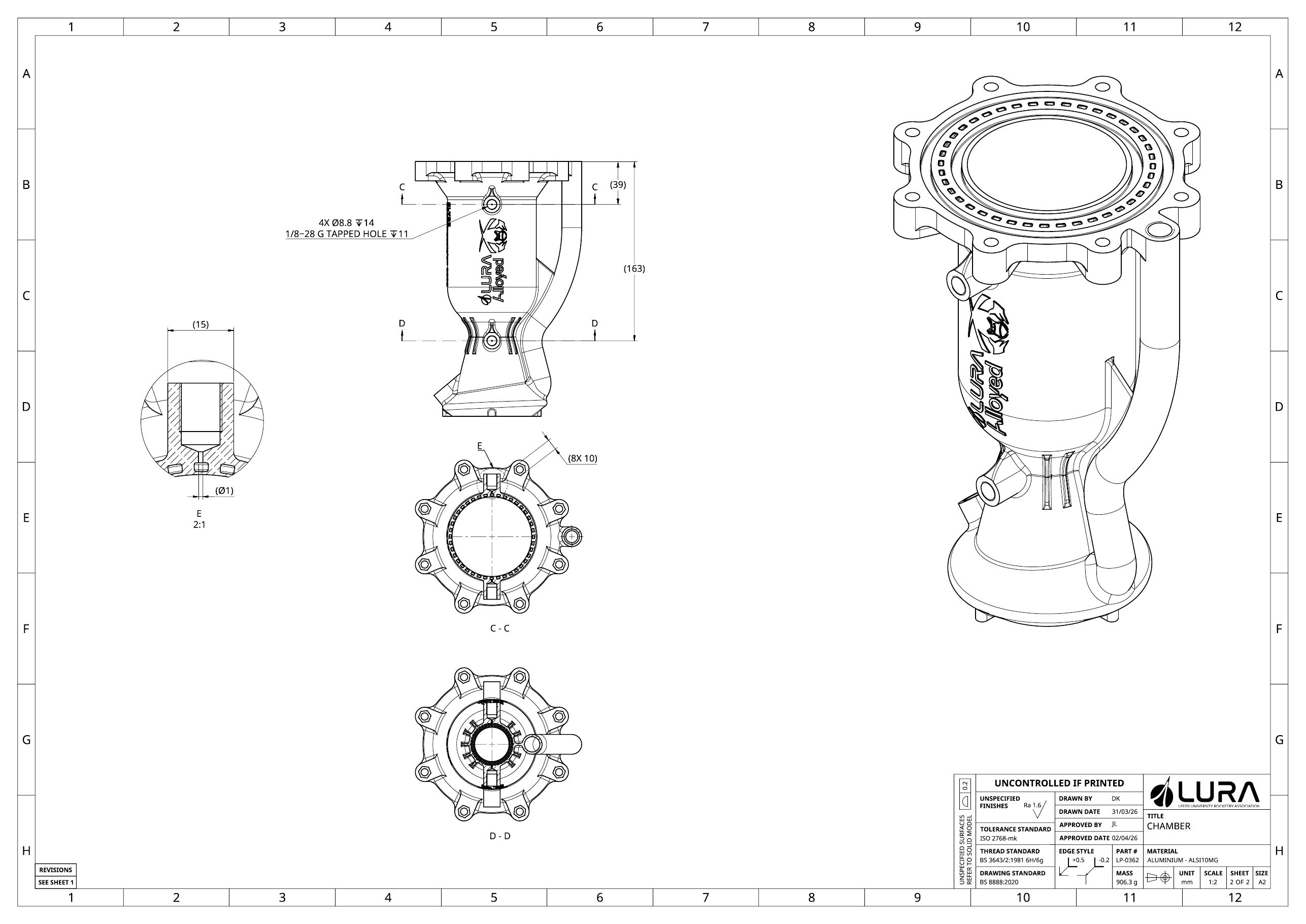
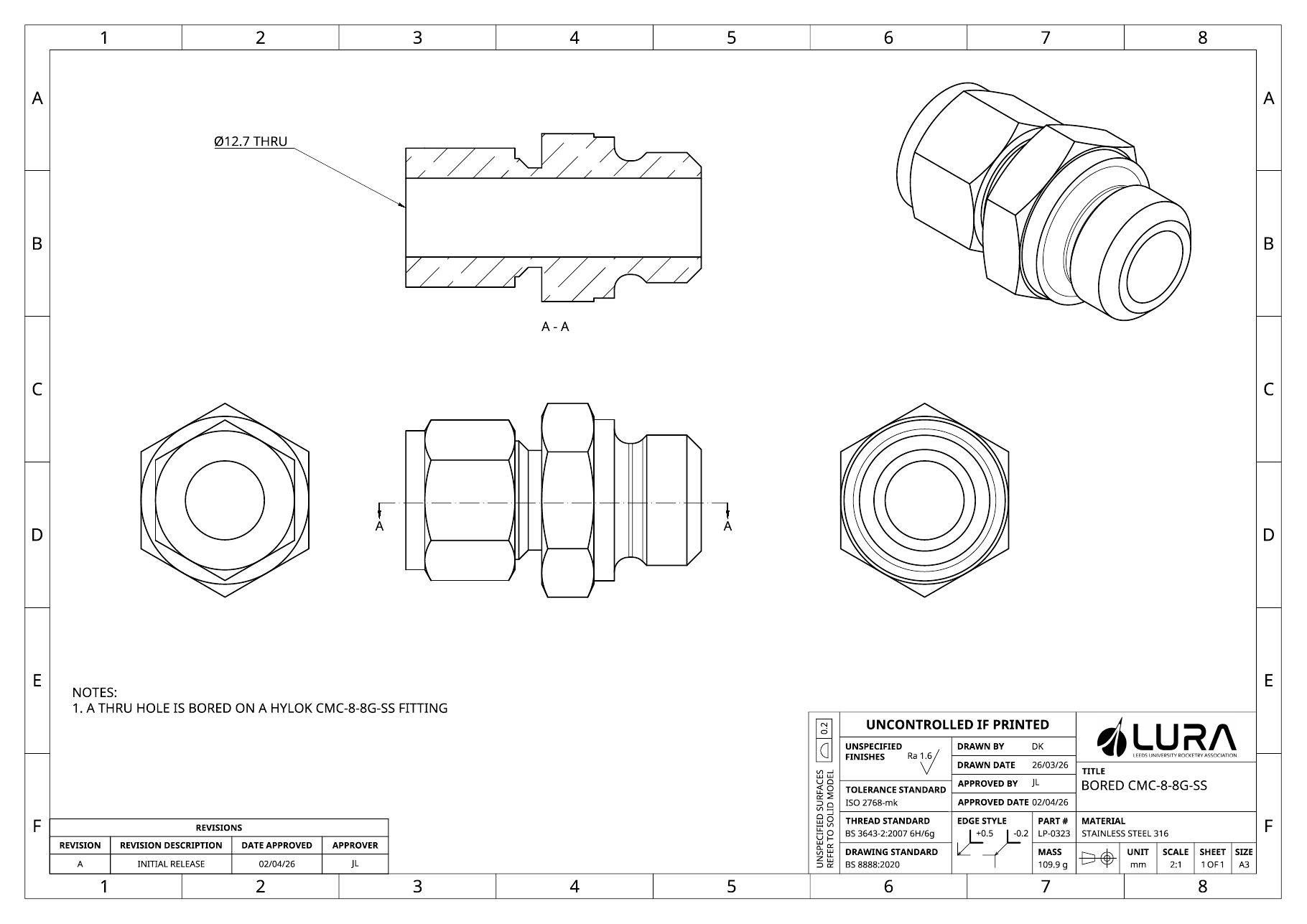
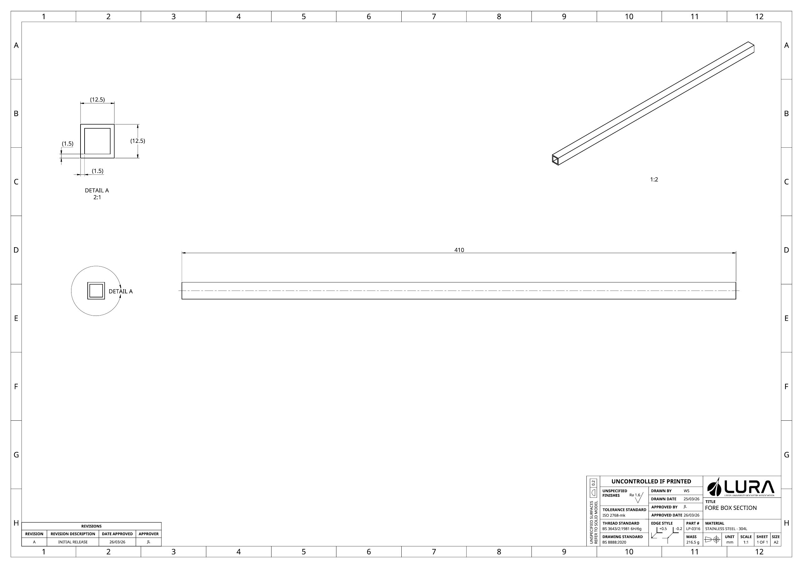
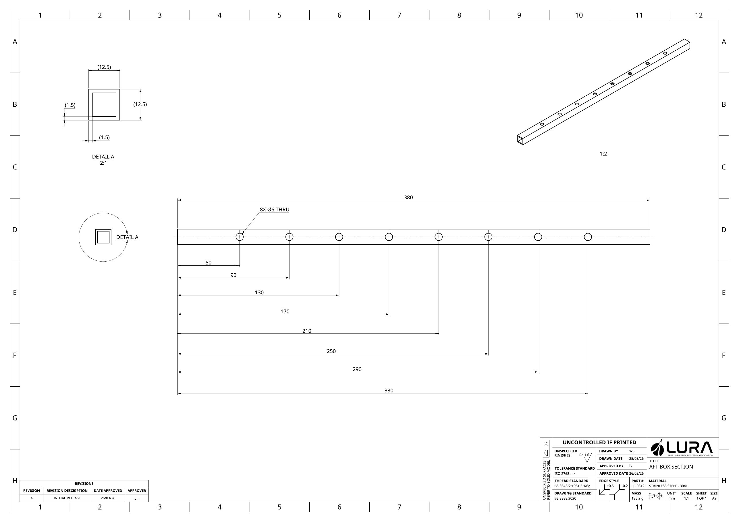
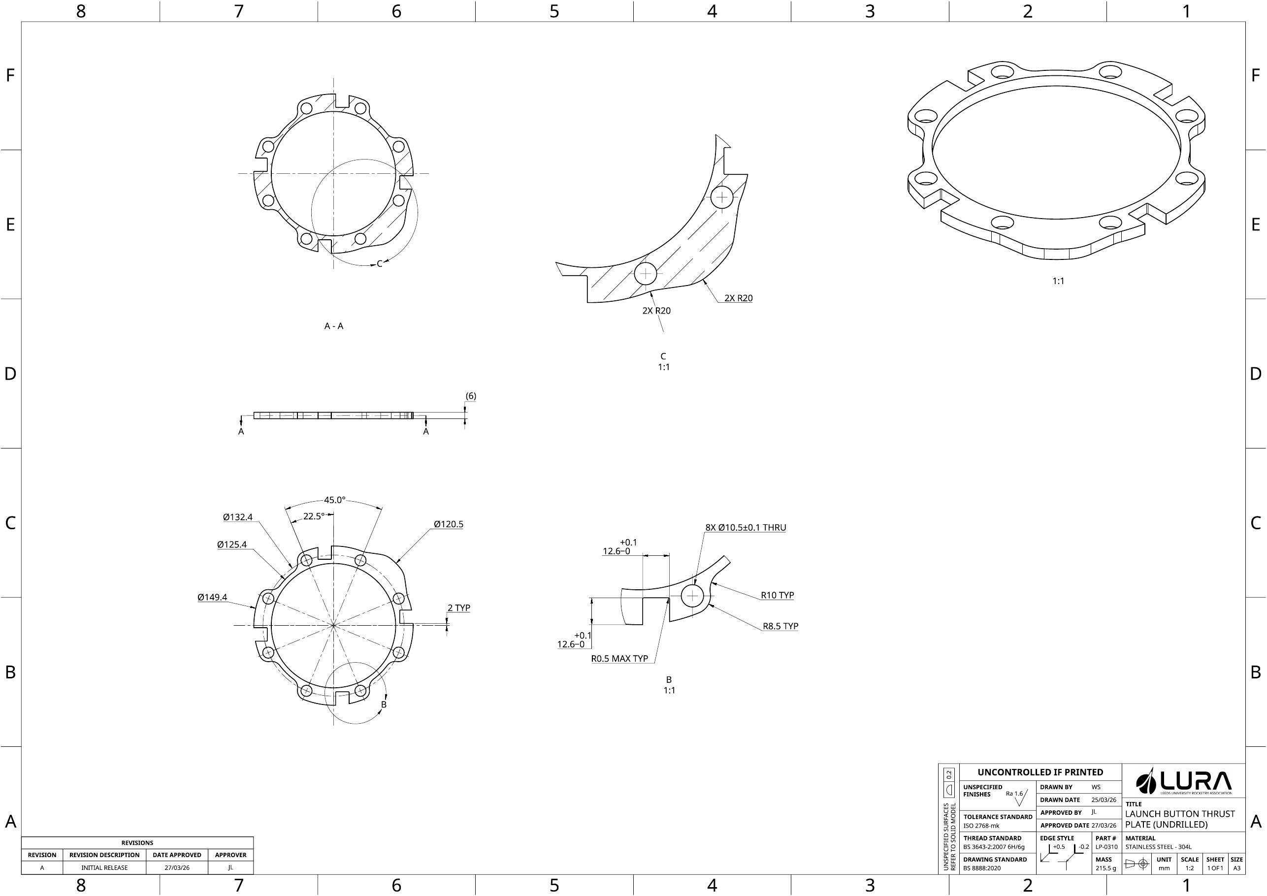
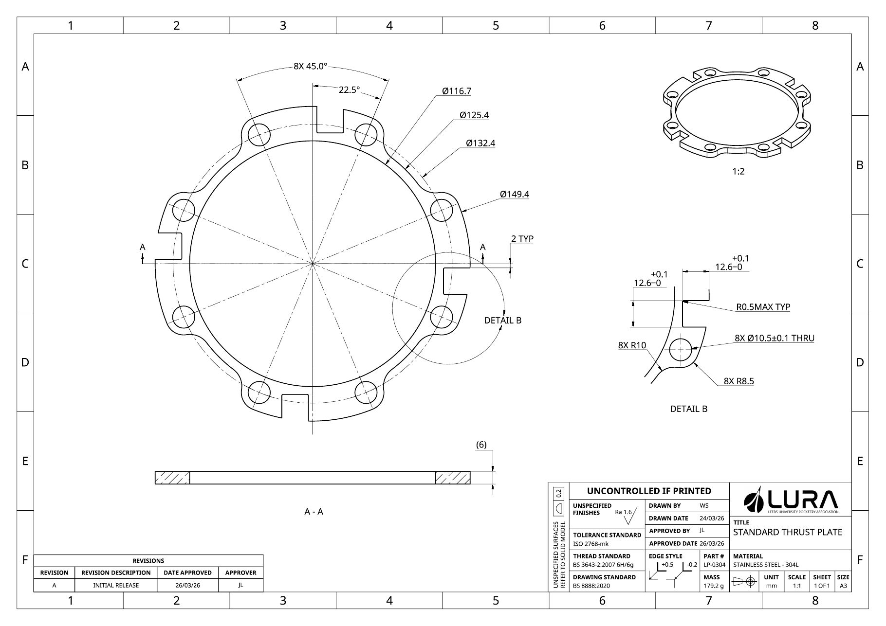
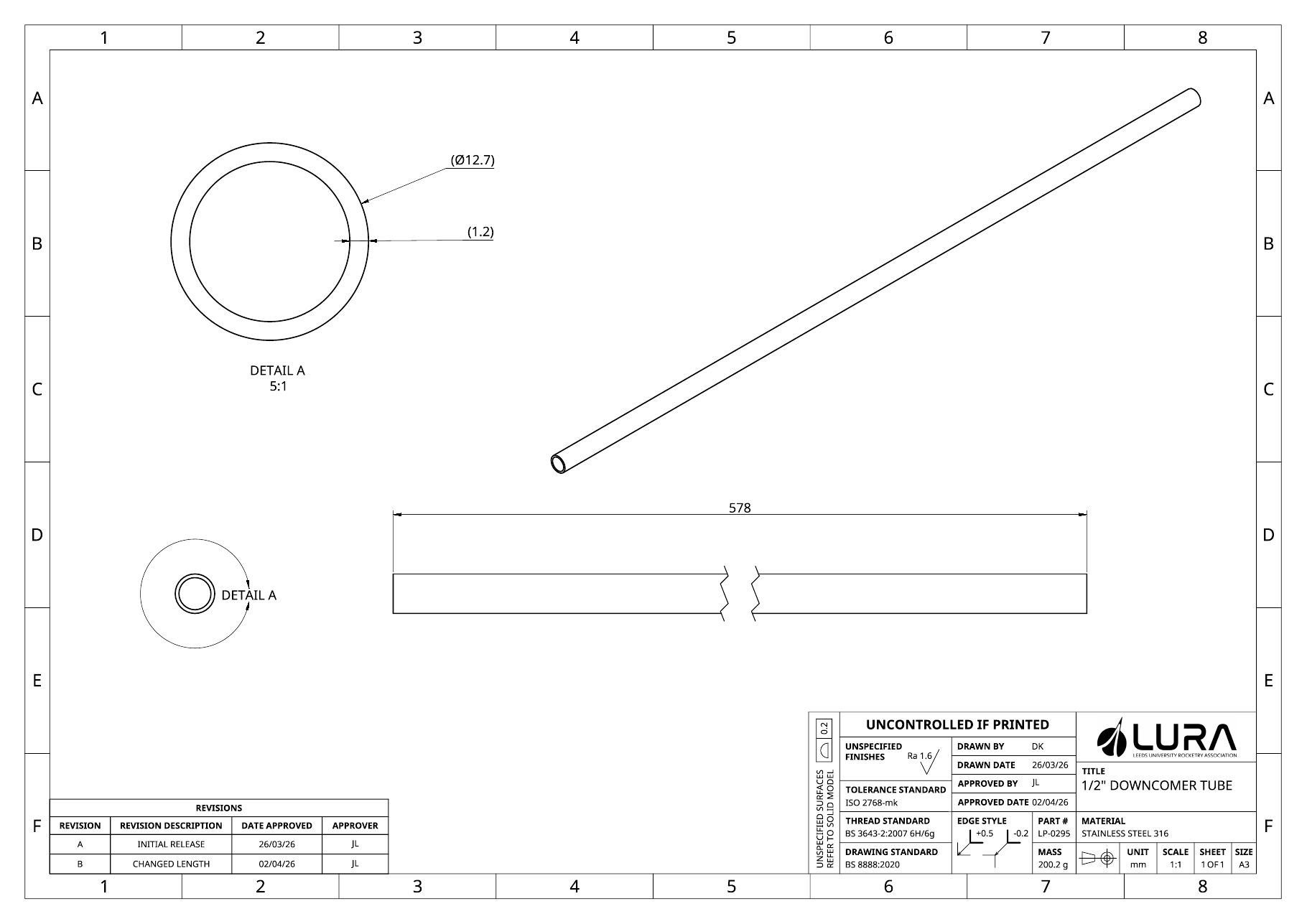
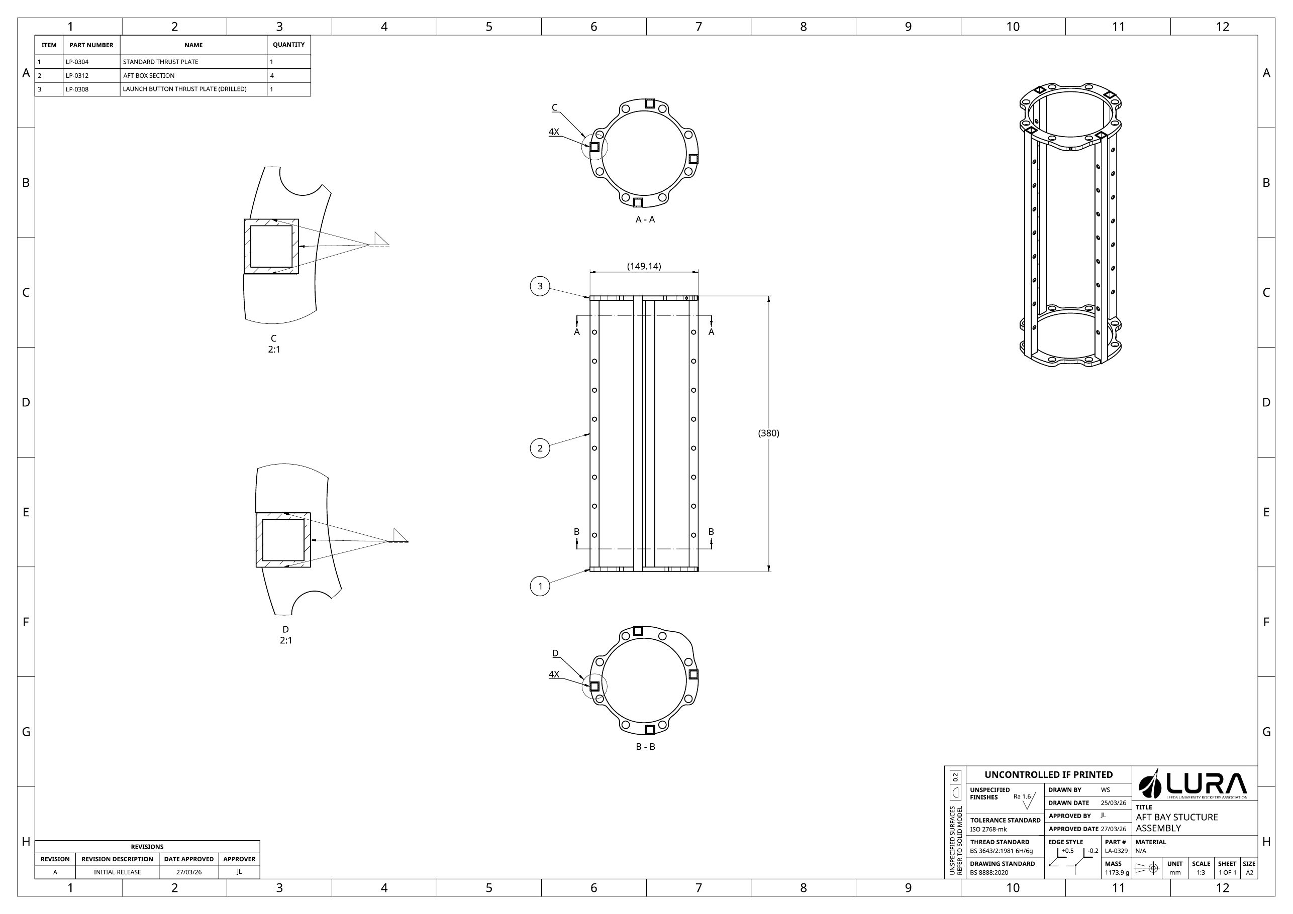
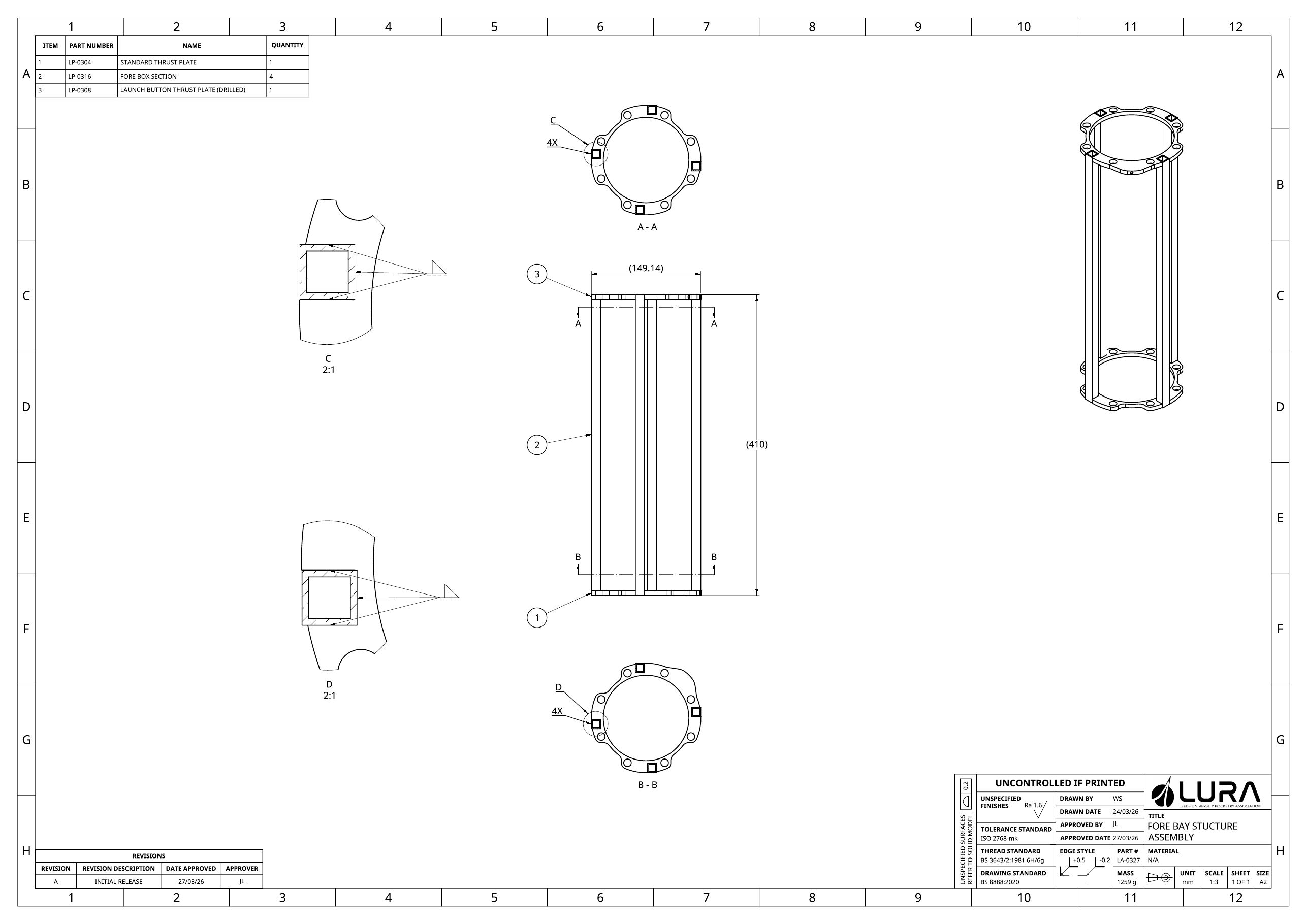
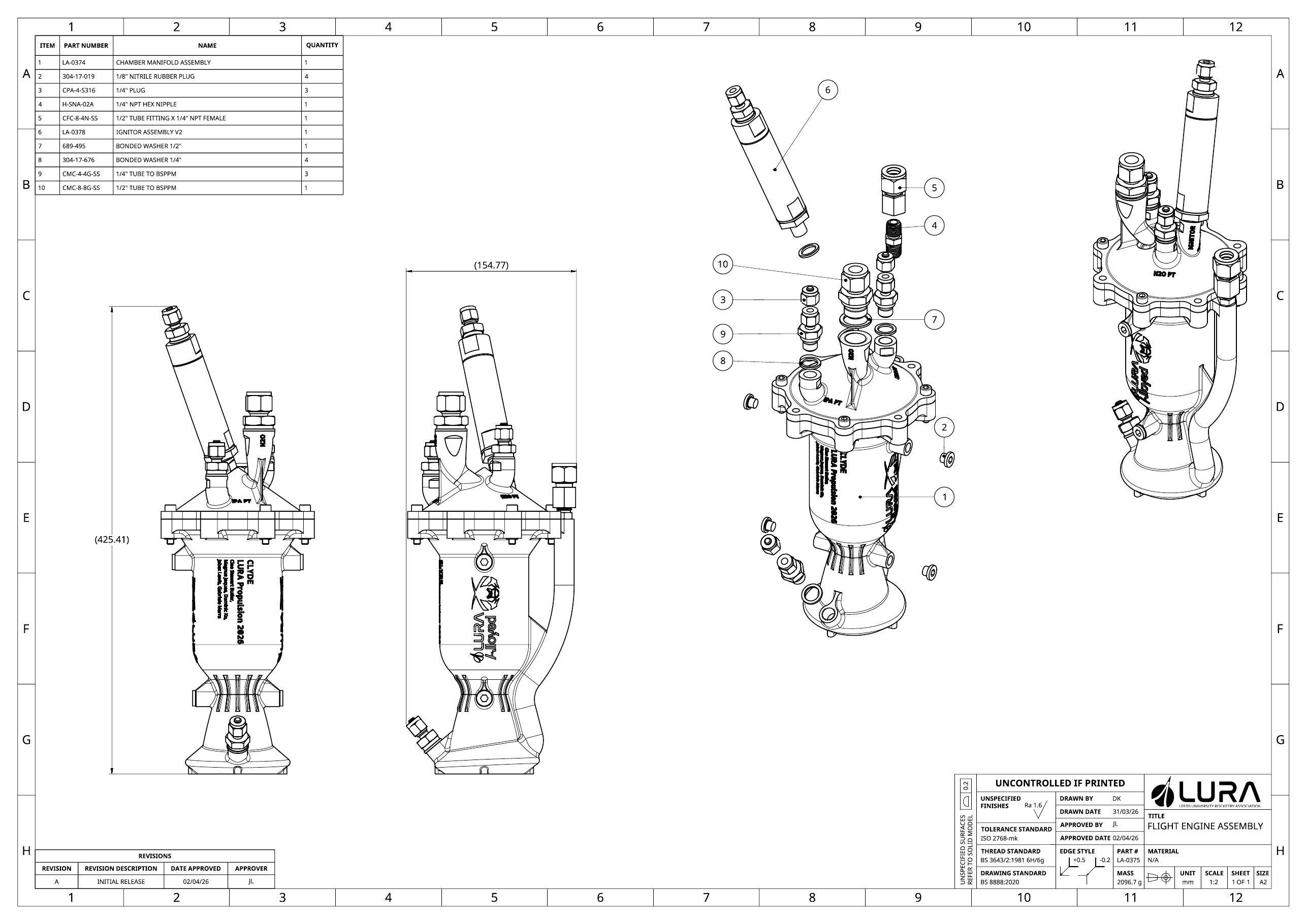
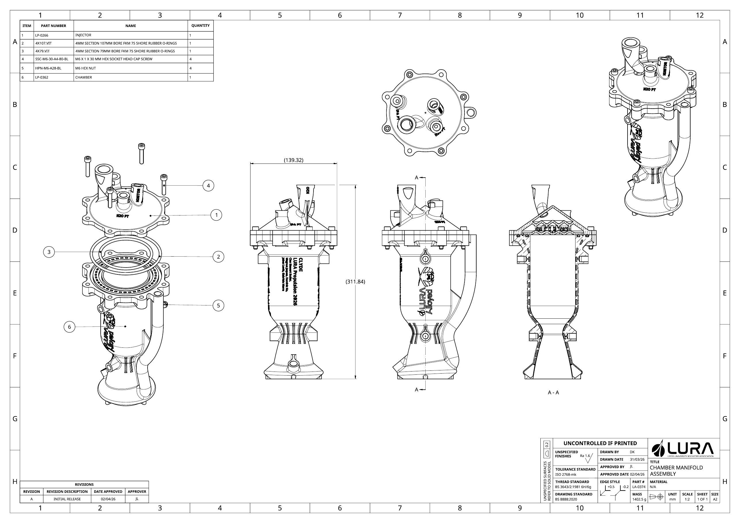
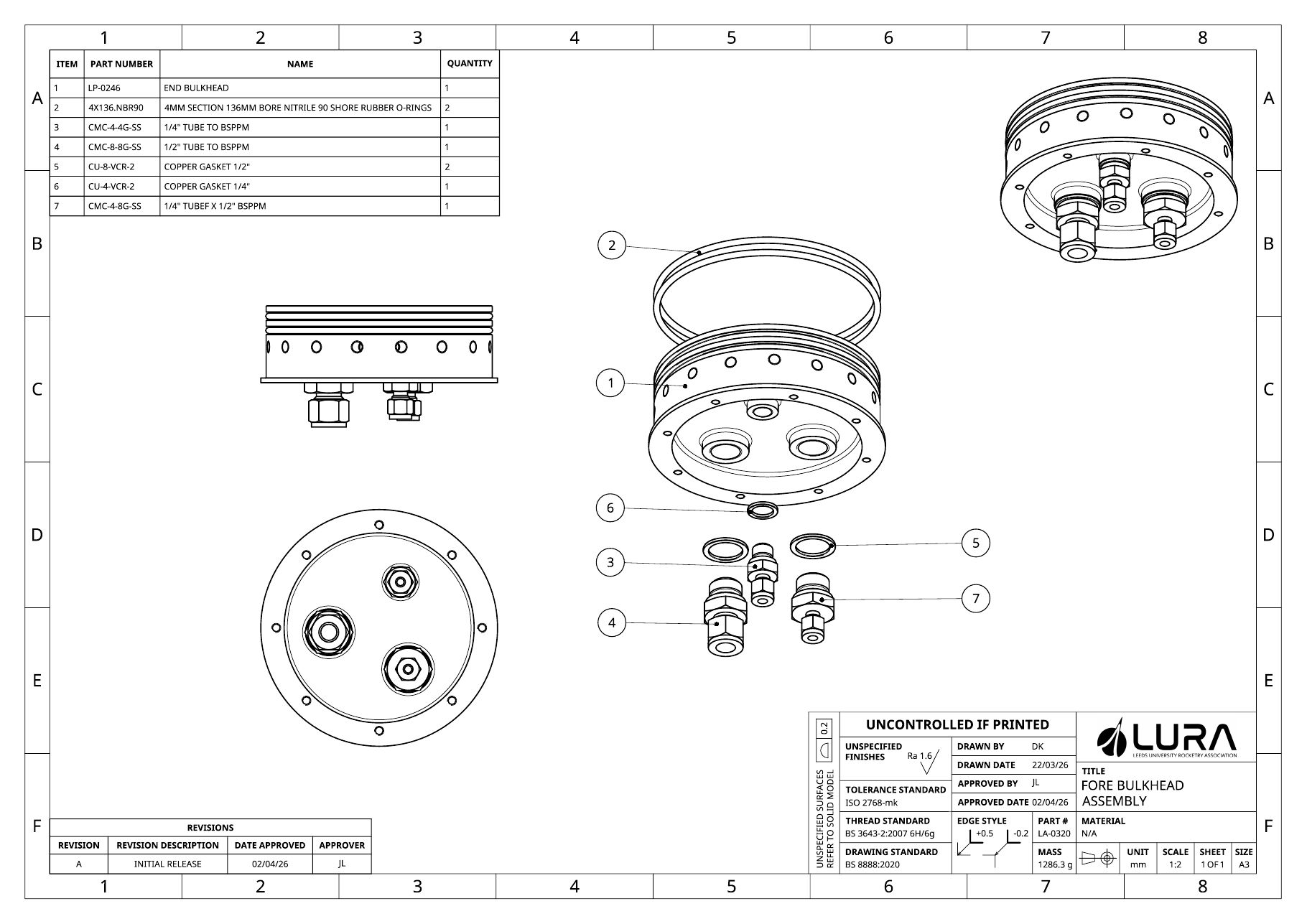
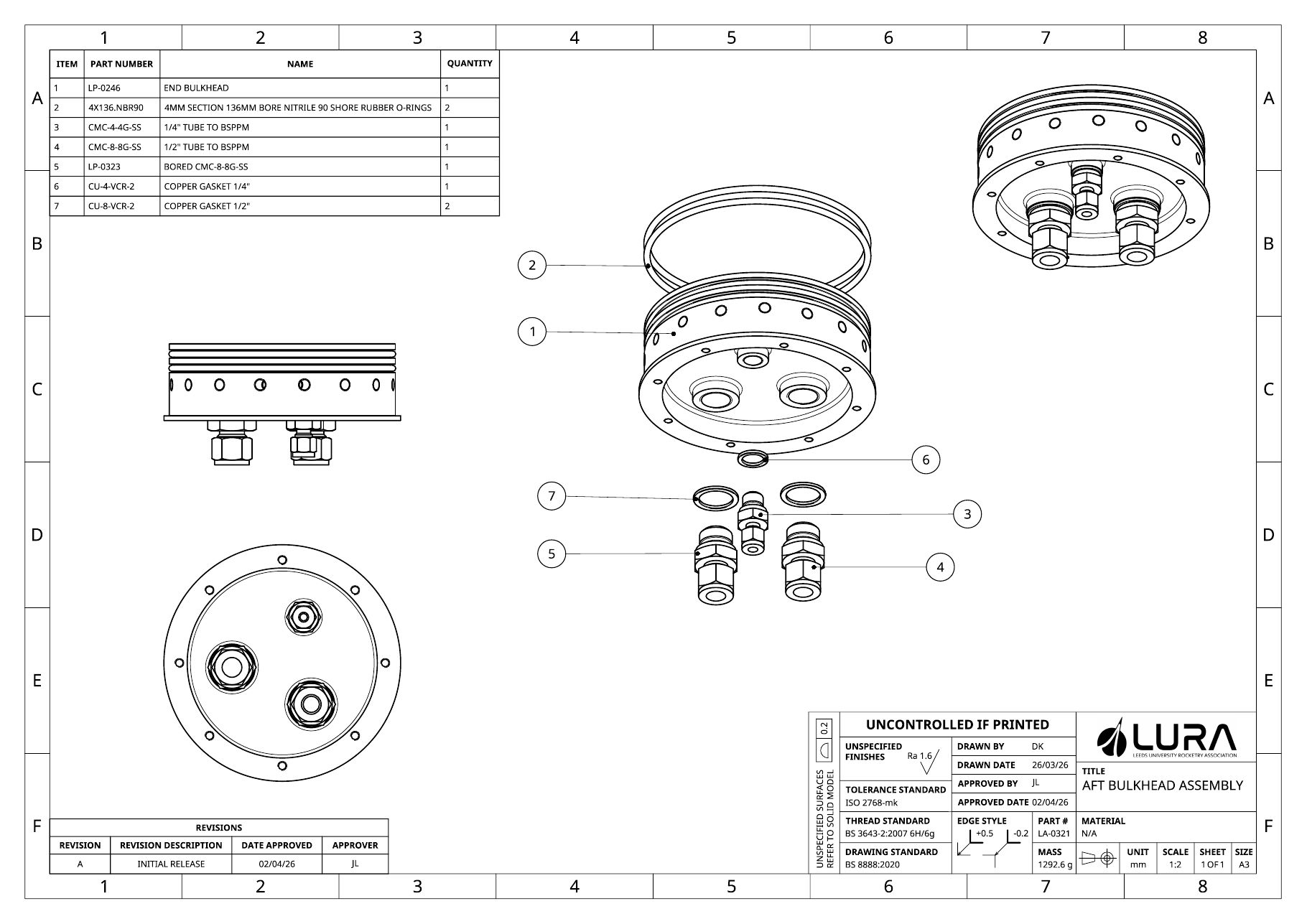
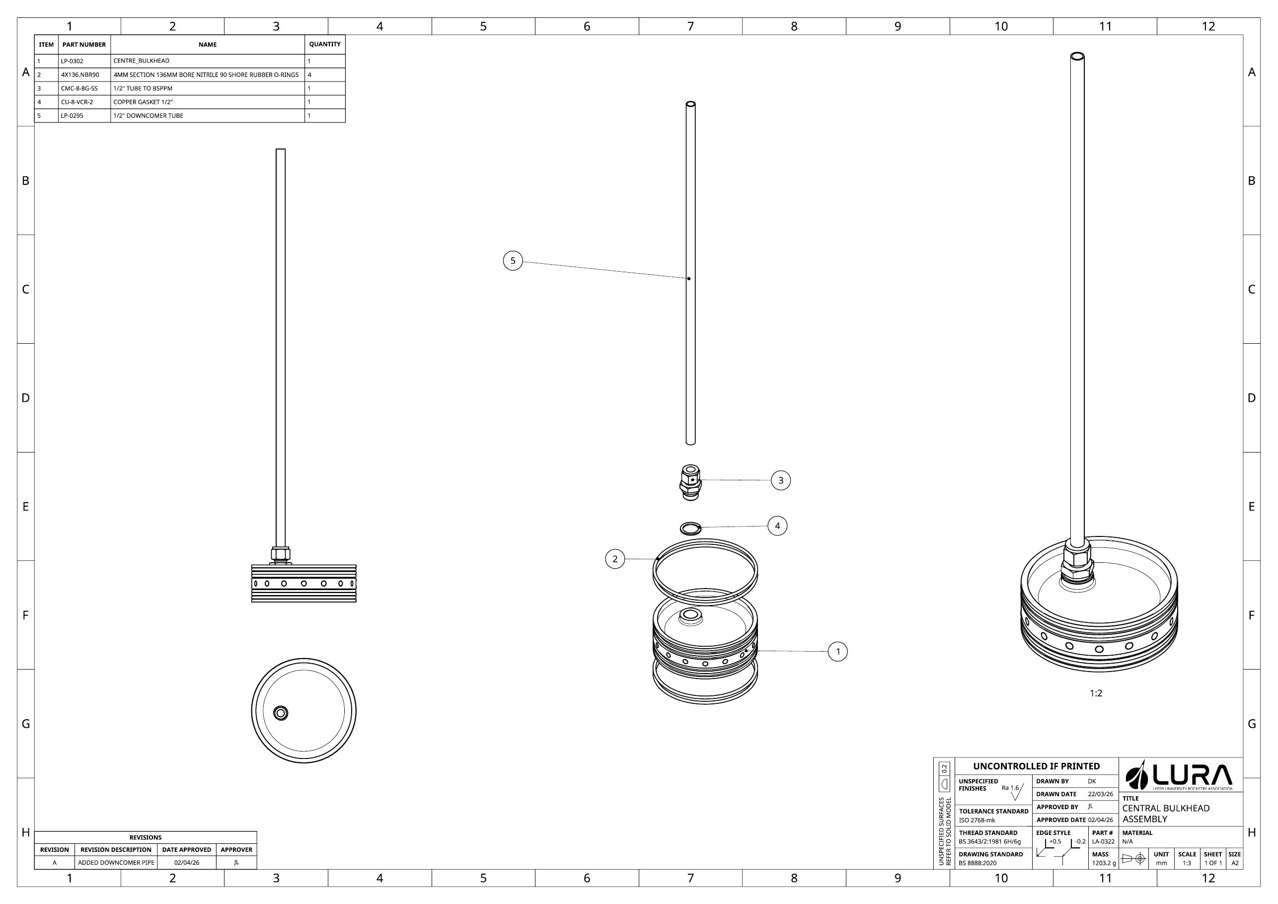
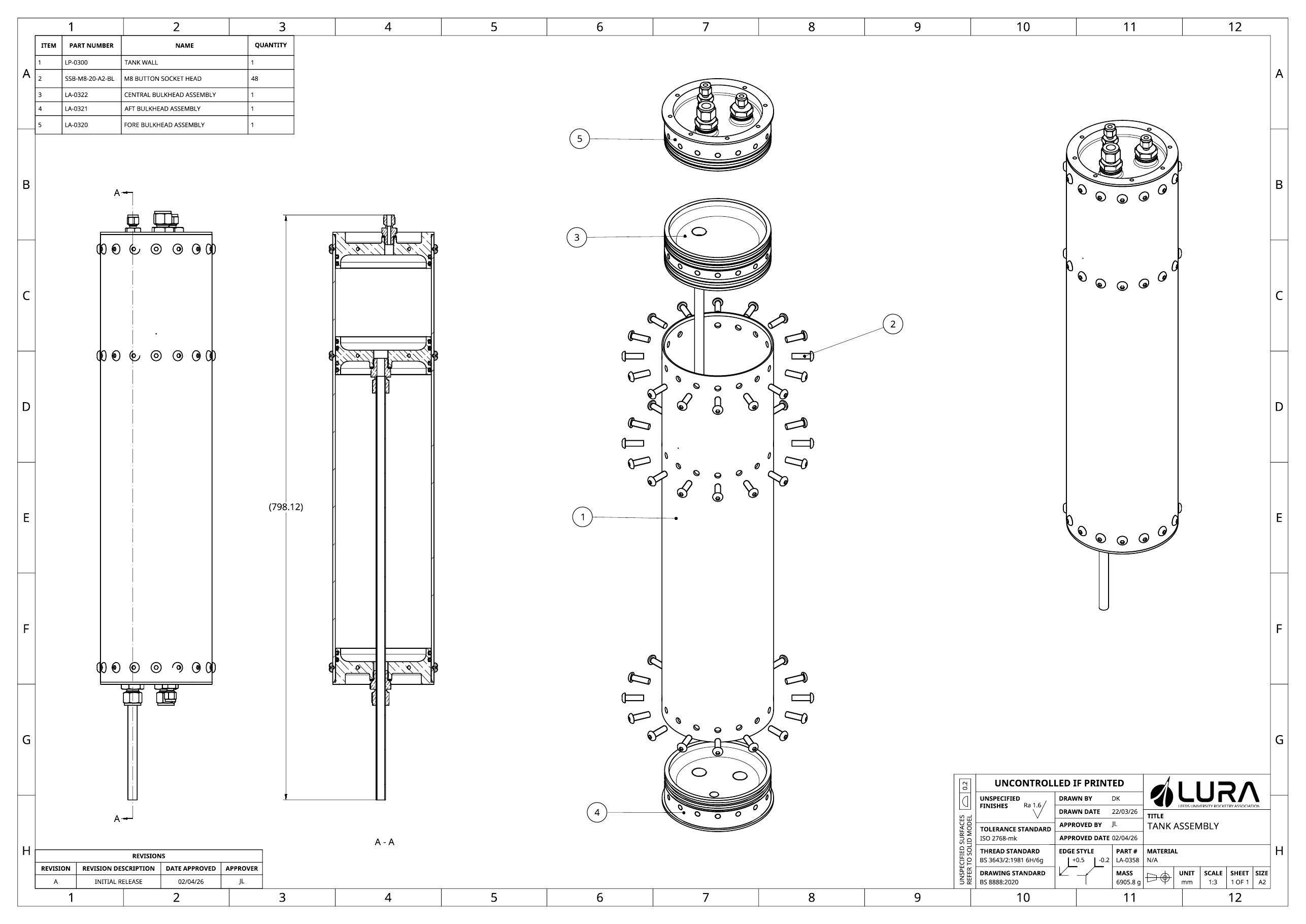
During this period, the team reshuffle had meant me stepping up to fill our empty chief engineer role. The fact this only happened mid-year meant that I missed out on the majority of the organisational management and was largely responsible for overseeing drawing releases, and system interfaces. The drawing pack for the liquid stack is here:
Testing
Prior to final integration, we hydrostatically tested the tank to 75Bar (1.5x the design max pressure of 50Bar).
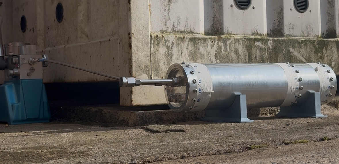
Hydrostatic test setup
We integrated the full system and took the rocket to the Sheffield Propulsion Laboratories' site for full stack testing.
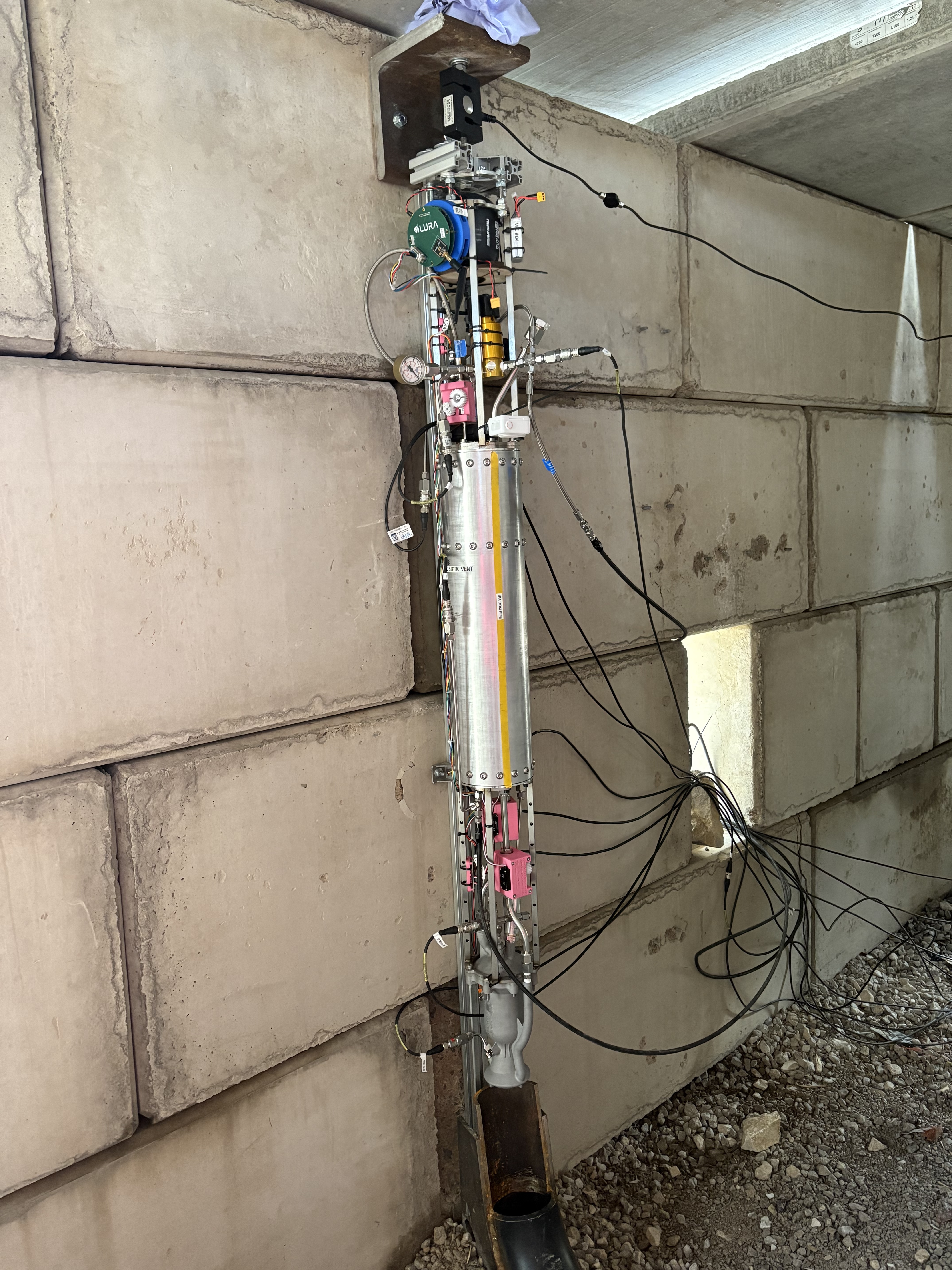
A massive accomplishment just getting to the site... but as soon as we arrived there was an issue. We had designed the entire system for 50Bar nitrous however, evaporative cooling meant we could only achieve 35.
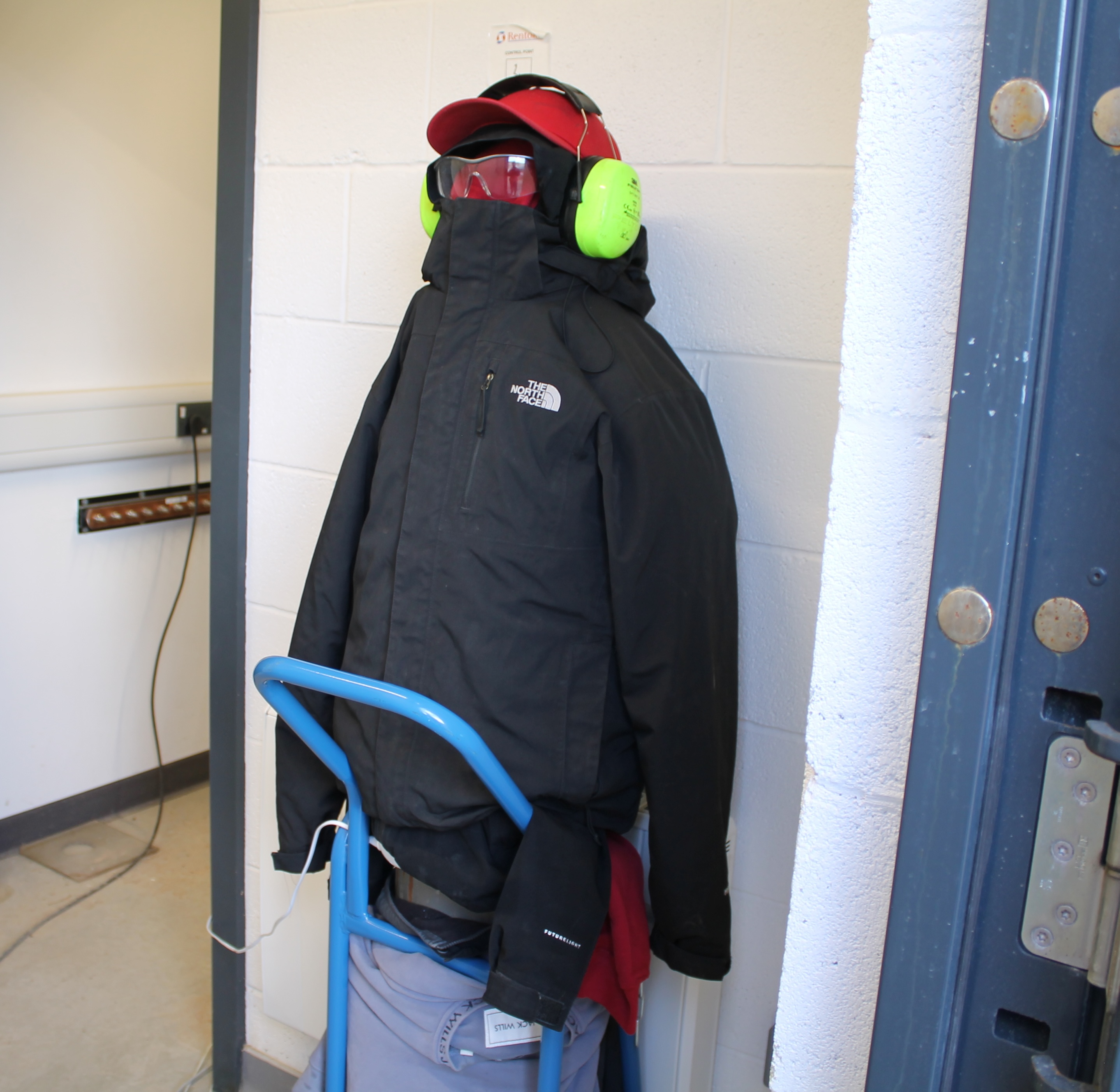
Our attempt to warm up our nitrous pre-fill. With full PPE of course
Accepting we would have a lower thrust, we tuned the IPA pressure to manage the OF - too ox-rich and the combustion would be too hot, too fuel-rich and it wouldn't ignite. Indeed, ignition issues meant that we got a few more cold flows than expected...
Luckily our test campaign straddled a weekend. After failure to get a hot fire, we got back to the workshop and re-assessed. I made a comprehensive excel sheet to determine the required IPA set pressure for a given N2O pressure on the day — and therefore predict the engine's performance using NASA CEA data.
When we returned on Monday, the rocket went straight onto the stand and were ready to start filling. Everything setup, everything ready to go. And we fired:
It wasn't perfect, but we built a liquid rocket! Not steady state, but 1.1kN of thrust just days after a mistake that could have ended the project.
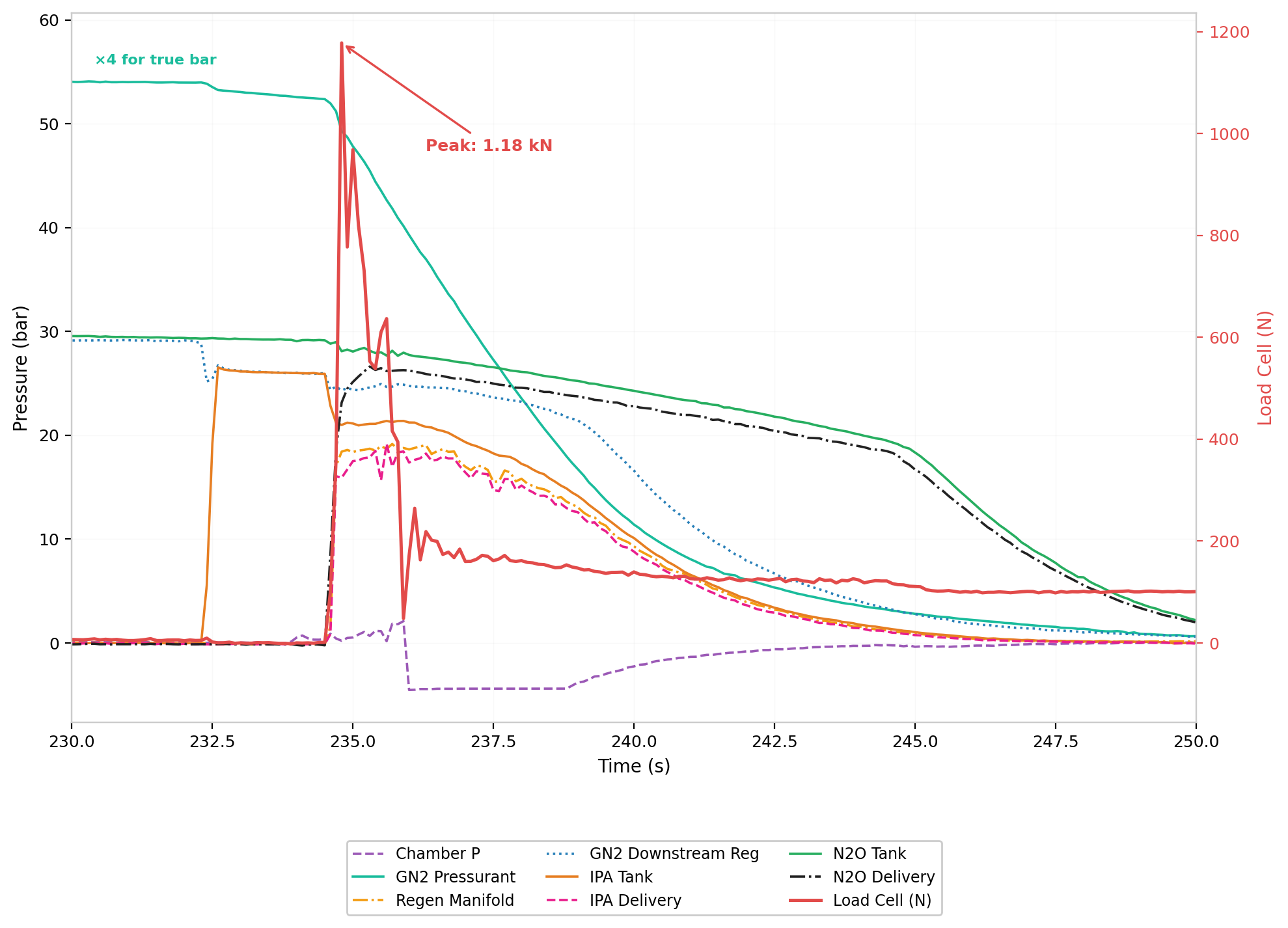
Hot fire thrust trace
Reflection
Ultimately, we were never going to be able to achieve the performance that we wanted without making hardware changes. Immediately following our test campaign, we sent our injector to have the nitrous orifices drilled out to increase the flow rate. The next available test slot is later this summer (2026), and so the team is working towards that. The dream to be the first liquid rocket launched from the UK is still alive!
But bigger than that - as a team we built something not very many people have. We did a lot of troubleshooting, a lot of supplier sourcing and a lot of high-level architecture decisions that future teams won't have to. Documenting our process, the lessons learned and the mistakes made has brought LURA a few steps closer to a Kármán line liquid rocket. If only someone had built a pump for it…